Practical Schemes for Fat-Tree Network Construction
Andre DeHon
Mon Nov 8 13:32:18 EST 1993
The initial target for the Transit network is an indirect, pipelined, circuit-switched network arranged in a multistage shuffle-exchange, bidelta configuration. The Transit bidelta network utilizes an advanced three-dimensional stack packaging scheme, low-voltage swing signals, matched impedance drivers, and a novel routing component (RN1) to achieve high-performance, low-latency interconnection between network endpoints [Kni89]. For moderately sized networks ( e.g. 256 processors), this network structure provides uniform low-latency interconnection between all processors.
However, even with three-dimensional packaging technology, the
distance between routing components grows as and the
number of routing stages grows as
as
, the number of
processors in the system, is increased. Due to limitations in signal
propagation speed, the increase in distance between routing components
translates directly into longer network clock cycles. The increase in the
number of routing stages effectively increases the number of pipeline
stages between network nodes and hence increases the communication latency.
In a bidelta configuration, all network interconnections thus degrade
uniformly in performance as the network is scaled to support more and more
processors.
This scaling problem, is not unique to the class of networks just described. This problem is inherent in all networks due to fundamental physical limitations. Signals cannot propagate faster than the speed of light. Components must be physically arranged in three-dimensional space, and wires of finite size must be routed in three-dimensional space. We cannot make components arbitrarily small. As the number of components in the system grows, we cannot keep them arbitrarily close to each other indefinitely.
Rather than accepting this uniform performance degradation as we scale upward to support more processors, we can optimize the interconnection scheme for locality. The idea is to take advantage of locality to minimize the impact of scaling on both aggregate network bandwidth and average network latency. In flat networks like the bidelta network, all processors are equally distant from each other. No locality can be exploited in the interprocessor communication. By allowing some nodes to be further away from each other in the network, other nodes can be placed closer to each other. With appropriate exploitation of the resulting locality, the average bandwidth is higher, and the average latency is lower than in a flat network configuration.
The network is based on Leiserson's fat-trees [Lei85] [GL85] in order to achieve a reasonable amount of locality and adequate bandwidth. Fat-trees are organized with hierarchical, tree-structured interconnections. As with any tree, nodes with lower common ancestors are closer to each other. In a fat-tree the channel capacity increases regularly between internal tree routing nodes toward the root of the tree. This increase in capacity accommodates the greater amount of traffic which may need to travel through internal nodes closer to the root of the tree. Leiserson's theoretical results show that with the proper allocation of channel capacity at each tree level, fat-trees are volume-universal networks. That is, for a given volume of hardware, a fat-tree is nearly the best routing network one can build, and the fat-tree can simulate any other network with at most a polylogarithmic degradation in time [GL85].
We provide fault-tolerance in the fat-tree organization utilizing Leighton's randomly wired redundant paths and random path selection among equivalent paths. The multiple redundant paths through the network make it possible to avoid faulty network components. Randomly wiring the redundant paths increases the tolerance of multiple faults [Lei90]. The random selection of a path among equivalent alternatives provides a computationally trivial, yet effective, mechanism for avoiding faulty portions of the network. [DKM90] describes this scheme for achieving fault-tolerance in multistage routing networks in some detail.
The fat-tree network described here is intended to be a practical network
that can be physically realized. Leiserson's theoretical fat-tree results
indicate that the architecture is physically realizable within the
limitations of three-dimensional spatial construction [Lei85]. The
construction technology and organization provides a high degree of
bandwidth [Kni89] [DKM90]. Leiserson's
theoretical work also shows that this architecture is at least as scalable
as any other network [Lei85]. The fat-tree can be built from simple
building blocks (see Sections and
) in highly
replicatable structures (see Section
), making the complexity of
constructing large networks practical. Finally, the fault-tolerance
inherent in the network construction makes the network reliable even when
scaled [DKM90] [LM89].
The RN1 routing component is used here as the lowest-level building block for fat-trees. Some of the details and specifics contained in this paper are closely related to RN1. However, the general construction topology and decomposition could be used with different routing components.
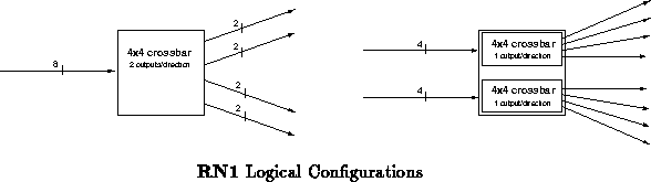
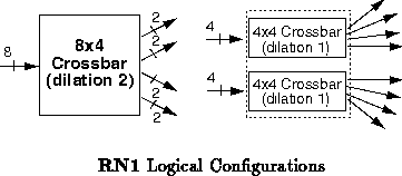
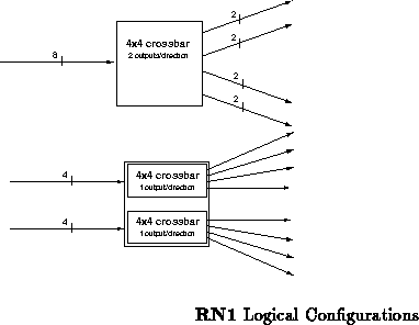
RN1 is a custom CMOS routing component currently under construction. It
provides simple high-speed switching for fault-tolerant networks. RN1 has
eight nine-bit wide input channels and eight nine-bit wide output channels.
These channels provide byte-wide data transfer with the ninth bit serving
as a signal for the beginning and end of transmissions. RN1 can be
configured in either of two ways, as shown in Figure . The
primary configuration is a
crossbar router with a dilation of
two. In this configuration, all eight input channels are logically
equivalent. Alternately, the component can be configured as a pair of
crossbars, each with four logically equivalent inputs and a
dilation of one.
Simple routing is performed by using the two bits of the first byte of a transmission to indicate the desired output destination. If an output in the desired direction is available, the data transmission is routed to one such output. Otherwise, the entire transmission is discarded. In either case, when the transmission completes, the RN1 routing component informs the sender of the connection status so that the sender will know whether or not it is necessary to retry the transmission. When both outputs in the desired output direction are available, the component randomly chooses which port to use.
To allow rapid responses to network requests, the RN1 routing component allows connections opened over the network to be reversed; that is, the direction of the connection can be reversed, allowing data to flow back from the destination to the source processor. The ability to reverse a network connection allows a processor requesting data to get its response quickly without requiring the processor it is communicating with to open a separate connection through the network.
RN1 is described further in [Kni89], [DKM90], and [Min90].
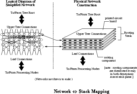
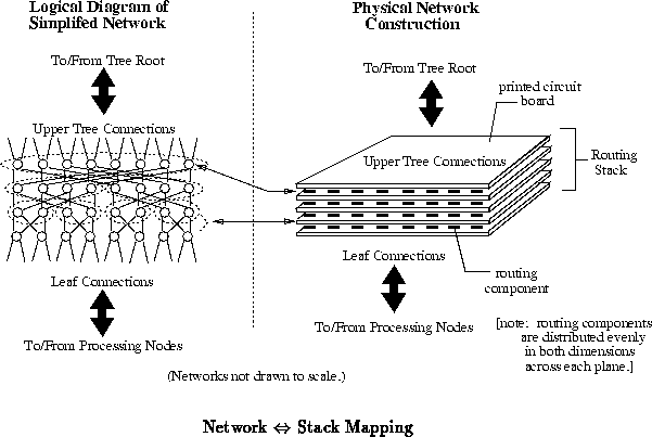
The basic packaging technology developed as a part of the MIT Transit
project is the three-dimensional stack. A stack is composed of
alternating layers, or planes, of components and printed circuit boards.
In a routing stack, the component layers perform switching while the
printed circuit boards interconnect routing components. The
interconnection provided by the printed circuit boards controls the desired
network topology. Figure depicts roughly how multistage
routing networks are mapped onto a routing stack. Figure
shows a more detailed cross-sectional view
of the layers in a routing stack. [Kni89] describes this stack structure in more detail.

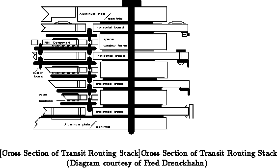

The stack structure does have its physical limits. Current printed circuit board manufacturing technology limits the size of a side of a stack to under two feet. However, the stack structure gives us a dense and efficient way of interconnecting routing components to build higher-level building blocks for network construction.
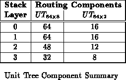
Using a routing component like RN1 with the stack packaging structure just described, we can build a few basic stack structures from which arbitrarily large networks can be built. The basic fat-tree stack primitive is known as the unit tree. Logically, a unit tree is organized as a piece of a fat-tree. Physically, each unit tree is composed of:
The down routing tree implements a simple quaternary tree where each parent
node forms the root of four subtrees (see Figure ). Routing
components in the down routing tree can simply route in one of four
directions to select among the four subtrees rooted at the routing components.

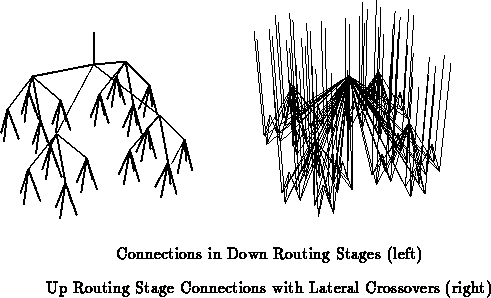

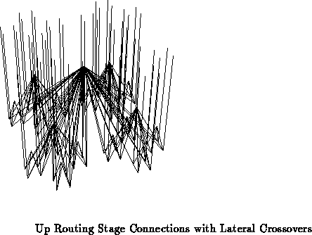
The up routing tree routes connections to the appropriate height in the
fat-tree. Routers in the up routing tree also direct connections in any of
four directions. Three of these directions route into the down routing
tree at each of the next three tree stages. These connections from the up
routing tree to the down routing tree make up the lateral crossovers. The
fourth direction routes the connection further upward in the tree.
Figure shows the logical routing performed by an up routing
stage, including the lateral crossovers.
Each unit tree implements three stages, or levels, of the fat-tree. The
unit tree has four layers of routing components. The top three layers
implement three stages of the down routing tree. The lowest layer
implements a single stage of up routing. One stage of up routing is
thus associated with each three down routing layers of fat-tree.
Figure shows the logical connections within a unit tree by
showing connections among four routing components, each from a different
stack layer.

Each unit tree has a single logical up routing channel leaving it for
higher stages in the fat-tree and a single logical down routing channel
entering from higher stages in the fat-tree. These connections to higher
stages in the fat-tree enter and exit the top of the unit tree stack.
Each unit tree also has logical up routing channels entering it
from lower tree stages or endpoints and 64 logical down routing channels
leaving it for lower tree stages. Connections to lower tree levels are
made through the bottom of the unit tree stack.
There are two unit tree configurations which match the organization just
described and fit neatly into the physical constraints of stack packaging
(Section ).
Both of these unit trees connect logical channels from 64 subtrees in the
fat-tree network to a single parent node (as shown logically in
Figures
and
). These unit trees differ in the
number of physical network connections composing each logical channel. The
unit tree provides eight input and eight output network connections
for each of its 64 subtrees, while the
provides two input and two
output network connections for each of its subtrees. The
unit tree
is roughly two feet square and two inches thick, while the
unit tree
is roughly one foot square and two inches thick. Table
summarizes the number of components composing each of these unit trees.
The number of routing components provides a metric for the cost and
complexity of each of these stack building blocks. Table
characterizes these unit trees by summarizing their channel organization
and capacity.

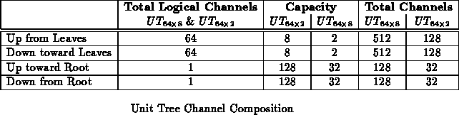
Processing nodes generally each have two inputs and two outputs to the
network [DKM90] to achieve fault-tolerance. This means that
unit trees can connect directly to processing nodes whereas
unit trees cannot. With the higher channel capacities, the
unit
tree is preferable for building all of the portions of the fat-tree network
which do not connect to the processors. Both of these unit trees are
arranged with redundant paths for fault-tolerance as described in
[DKM90]. The final stage of down routing in the
unit
tree is constructed out of RN1 routers configured in their dual
crossbar mode such that each of the outputs to a node comes from a
different routing chip.
As mentioned in Section , one desirable property of fat-trees
is their volume-universality. This property guarantees that a fat-tree can
efficiently simulate any other network of comparable volume within a
polylogarithmic time factor [Lei85]. Additionally,
volume-universality guarantees that larger and larger fat-trees can be
created by simply adding tree levels and scaling the basic structure within
the three-dimensional world.
To retain volume-universality in a quaternary fat-tree, the channel
capacity must on average grow by a factor of on each
successive level toward the tree root.
This growth rate
follows directly from the fact that the volume of processors being
interconnected increases by a factor of four at each successive tree level
and the fact that the channel capacity available for routing communications
increases proportionally to the surface area of that volume. Looking at
the channel capacity summary in Table
, we see that the
capacity of a logical channel increases by a factor of 16 through the three
tree levels contained in the unit tree. On average, this gives the desired
channel capacity growth rate of
.
Using unit trees, we can easily construct large fat-tree
networks. These fat-tree networks are built in stages of unit trees where
each unit tree stage is composed of many unit tree stacks and makes up
three tree levels of the fat-tree. Each additional stage of unit trees
multiplies the number of processors supported by the fat-tree by 64.
At almost all points in the fat-tree, the channel capacity of a channel in
a logical subtree is greater than the eight physical channels provided by
the unit trees. The larger channel capacity is handled by using
multiple
unit trees to construct the logical parent nodes for such
subtrees. The connections from the subtree unit tree stacks into the
parent node unit tree stacks are dispersed as widely as possible; that is,
physical channels from a single unit tree in the bottom tree are spread out
as evenly as possible to all unit trees comprising the parent nodes.
Spreading these redundant paths to and from subtrees as widely as possible
among the parent trees further increases fault-tolerance. Proper
dispersion makes it possible to remove entire unit tree stacks anywhere,
except at the leaves, and still have a functionally complete fat-tree;
performance is, of course, degraded when unit tree stacks inside the
fat-tree network fail or are removed.
It is illustrative to consider some concrete examples of fat-tree composition.
From channel capacity arguments, we see that the number of unit trees
in a parent stage is always a factor of four smaller than the number of
unit trees in the immediate child stage, as long as unit trees of the same
size are used in both stages. At each internal unit tree stage, unit
trees form the root of each subtree. Sixty-four subtrees connect to one
logical parent node composed of
unit trees. The area
which must be interconnected thus increases by a factor of 16 at each
stage.
Given these growth characteristics, there is no recursive,
three-dimensional structure that keeps interstage interconnection distances
constant. This is easily seen by noting that the number of components
grows exponentially with the number of tree levels, while the number of
candidate locations for the placement of components in three-dimensional
space is bounded by cubic growth. Therefore, the interstage delay must
grow between successive stages as the system is scaled up in size. Since
number of processors supported by a network with stages of unit trees
is
, the system grows rapidly and will require only a few stages even
for very large systems.
A natural approach to accommodating this 4 to 1 area convergence
(Section ) in a world limited to three dimensions is to build
hollow cubes. If we select one face as the ``top'' of the cube, the four
adjacent faces accommodate four times the surface area of the top and
naturally four times the number of unit tree stacks of a given size. As
such, the ``sides'' contain the converging stacks from one level, and the
``top'' contains the unit tree stacks at the next level up the tree to
which the ``side'' stacks are converging. The ``bottom'' remains open,
free of stacks. The ``bottom'' could be used to shorten wires slightly,
but utilizing it in that manner would decrease accessibility to the cube's
interior. Figures
and
show this basic hollow
cube structure.
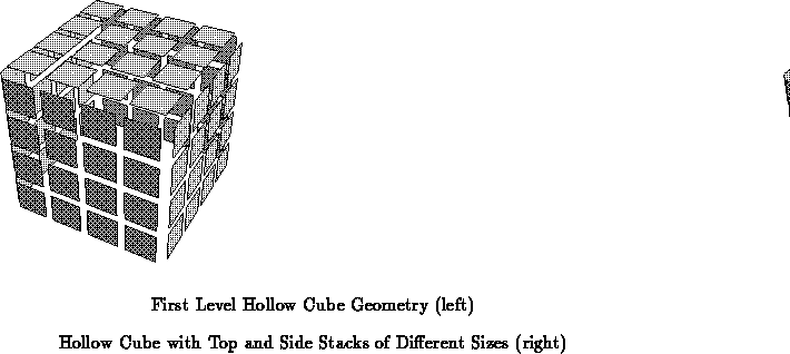


At the next stage of convergence, the hollow cube unit just described is
treated as the base unit. Each such unit can be arranged so that its
``top'' is treated as the basic unit structure for the next stage. We then
arrange 16 of these basic units into a square with 4 basic units on each
side. A plane of unit trees of size equal to each of the sides is then
used for the ``top''. The next hollow cube stage is shown in
Figure as the natural extension of Figure
. This
progression can be continued in a recursive manner ad infinitum
allowing arbitrarily large fat-tree networks to be constructed.

The hollow cube configuration seems practical while giving reasonable performance for the sizes of interest during the next decade. It is not known to be optimal for minimizing the interstage wiring distances. Finding an optimal solution which retains sufficient accessibility is still an open issue. While this hollow cube structure may not be the most compact structure, it does exhibit a number of desirable properties.
When interconnecting unit tree stack stages, physical channels out of the top of one set of unit trees connects to channels out of the bottom of another set. The channel capacity interconnecting the stages of stacks is thus largely surface area limited. The hollow cube structure allows maximum exposure between the surfaces that need to be connected.
Since the structure is ``hollow,'' connections can be wired through the
free space in the center, making the maximum wire length only
times the length of a side. Every time the number of processors increases
by a factor of 64, the maximum length increases by roughly a factor of four
due to the factor of four growth in side size associated with each
additional level of the hollow cube.
In the hollow cube geometry, individual stacks are reasonably accessible for repair. Since the cubes are hollow, it is possible to access any individual stack without moving any other stack. This accessibility allows repair and inspection without interfering with the bulk of the network operation. The numerous wires inside the cube may decrease accessibility, but that effect can be minimized using optical interconnection ( e.g. [WBJ +87] [BJN +86]) across the free-space in the center of the cube. The ``missing'' sixth wall of the cube can be used to allow entrance into the center of the structure for maintenance and repair.
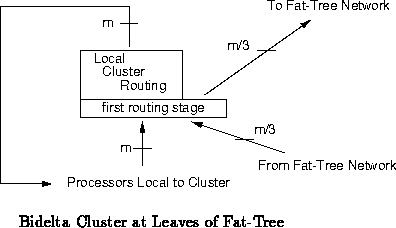
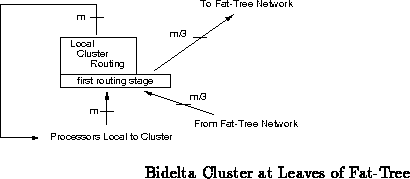
Fat-trees allow us to exploit a considerable amount of locality at the expense of lengthening the paths between some processors. Bidelta networks fall at the opposite extreme of the locality spectrum where everything is uniformly close or distant. Another interesting structure to consider is a hybrid fat-tree. A hybrid fat-tree is a compromise between the close uniform connections in the bidelta network and the locality and scalability of the fat-tree network. In a hybrid fat-tree, the main tree structure is constructed exactly as described in previous sections. However, the leaves of the hybrid fat-tree are themselves small bidelta networks instead of individual processing nodes. With small bidelta networks forming the leaves of the hybrid fat-tree, small to moderate clusters of processors can efficiently work closely together while still retaining reasonable ability to communicate with the rest of the network.
The only additional building block needed to build hybrid fat-trees is
the bidelta leaf cluster stack. A bidelta leaf stack is constructed
in much the same way as a Transit bidelta stack [Kni89]. A
bidelta leaf stack is composed of several stages of switching. Each stage
switches among four logical directions. The first stage is unique in that
only three of the four logical directions through the first stage route to
routers in the next stage of the stack. The fourth logical direction
through the first routing stage connects to the fat-tree network. The
remaining stages in the bidelta leaf stack perform routing purely within
the leaf cluster. To allow connections into the leaf cluster from the
fat-tree portion of the network, one-fourth of the inputs to the first
routing stage come from the fat-tree network rather than from the leaf
cluster processing nodes. Figure shows a diagram of a
bidelta leaf cluster. Bidelta leaf clusters which support 12, 48, and 192
processing nodes can be easily constructed using RN1 and the current
packaging technology (Section
); these bidelta leaf stacks are
referred to as
,
, and
, respectively.

Hybrid fat-trees are constructed identically to standard fat-trees.
Bidelta leaf clusters appear at the lowest level of the tree instead of
unit trees.
unit trees form the inner tree nodes. The
hollow cube geometry (Section
) accommodates the bidelta leaves
nicely.
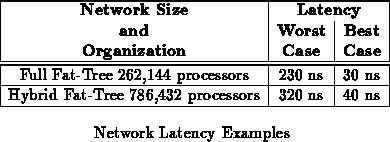
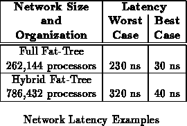
Latency in the unit tree based network is superior to the latency of a naive implementation of a fat-tree network in a number of ways. Skipping tree stages on the route up the tree reduces the number of stages of routing incurred while traveling toward the root by roughly a factor of three. Utilizing the RN1 component, which is a constant sized switch, keeps the routing delay at each stage constant at the cost of incomplete concentration. Schemes described in [DeH90] allow the clock cycle for switching to run at a rate independent of the signal delays incurred while crossing long wires. A long wire only affects the latency of a connection which actually traverses it.
Using the RN1 routing component running at 100 MHz and suitable
technology assumptions, Table shows the latency for two
representative fat-tree networks. The latency given in Table
represents the time required to send data through the network from one
endpoint to another assuming the connection is made successfully.
[DeH90] provides the derivation of these latency figures,
including the assumptions made. Section
below describes the
probability of successfully opening a connection through the network.
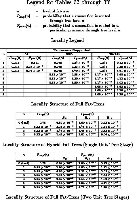
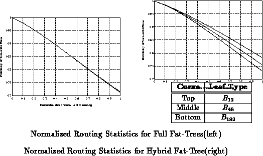
When building large networks supporting on the order of thousands to
millions of processing nodes, it is clear that locality must be exploited
to obtain reasonable performance. The fat-trees and hybrid fat-trees
described in this paper each have a natural architectural locality.
Tables through
summarize the locality
structure for several of these fat-tree structures. The relative merit of
each of these network architectures is highly dependent on the
corresponding locality structure which can be exploited in the
communications which utilize the network. In order to achieve optimal
performance, the communication patterns in programs should exhibit locality
comparable to the architectural locality of the network.

Tom Knight originally suggested the idea of using fat-tree structures as a means for scaling Transit networks. Tom Knight and Henry Minsky were invaluable for discussion and criticism of these ideas throughout the development process. Discussions with Tom Leighton, Charles Leiserson, and Alex Ishii were valuable to my understanding of the more theoretical aspects of network organization. Pat Sobalvarro was helpful in providing the basic tools for the probabilistic analysis. Fred Drenckhahn is responsible for fleshing out many of the ideas in the Transit packaging scheme. Thanks to Tom Knight, Mike Bolotski, and Ellen Spertus for commenting on early versions of this paper.