Previous: Instructions Up: Structure and Composition of Reconfigurable Computing Devices
In this chapter, we put together the sizings from
Chapter and
, the growth rates from
Chapter
, and the instruction requirements from
Chapter
to form a unified area model for RP-space,
a large class of reconfigurable processing architectures. The area model
gives us a first order size estimate for reconfigurable computing devices
based on the key parameters identified in the previous chapters. We use
this model to estimate peak computational density as a function of
granularity and on-chip instruction store sizes. We also use it to
characterize the way computational efficiency decreases as application
granularity and path lengths differ from the architecture's optimal points.
We assume an array of homogeneous, general-purpose processing elements. For pedagogical purposes, no special-purpose processing units are included. The area for each bit processing element is taken to include:
Table summarizes the parameters used in
Equation
.
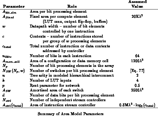
is typical of static memory, which we
will assume here. Memory cells packed into large arrays are likely to be
denser, on average, than small arrays or isolated memory cells. Dynamic
memory cells may be a factor of four smaller in large arrays, where
appropriate.
Equation assumes that interconnect area is
proportional to the number of switches. In Sections
and
, we saw that switch growth rates match
or determine interconnect growth rate. In
Section
, we did see that wiring might
dominate switch growth for large
, which is not accounted by
Equation
.
is a constant of
proportionality intended to match the number of switches to the empirical
interconnect areas typically seen rather than a model of any particular
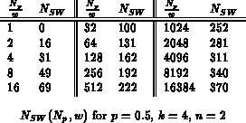
interconnect geometry. Table
summarizes the number of switches
as a function of
and
for
, as will be used here. This
is the same data which was plotted in Figure
; for
, the only difference is that we use
as the network
size when determining
(See
Equation
).
For devices with multiple contexts, a controller manages the
selection and sequencing of instructions in the array.
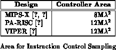
The area we use for is a rough estimate based on a sampling of
processor implementations (See Table
). We assume
that the area in the controller is proportional to the number of
instruction address bits,
.
FPGAs traditionally have a single context, making
, while
processors have controllers composing the program counter and branching
logic.
Using the model, we can examine the peak computational densities
from various architectural configurations in RP-space.
Figure plots computational density against datapath width,
, and the number of instructions per function group,
. As
increases there is more sharing of instruction memories and less switches
required in the interconnect resulting in smaller bit processing element
cell sizes or higher densities. As
increases, there are more
instructions per compute element resulting in lower densities. The effect
of more instructions is more severe for smaller datapath widths,
, since
there are less processing elements against which to amortize instruction
overhead.
For single context designs, there is only a factor of 2.5
difference in density between single bit granularity and 128-bit
granularity. At this size, network effects dominate instruction effects,
and the factor of difference comes almost entirely from the difference in
switching requirements. For heavily multicontext devices at the
same number of instruction contexts, the difference between fine and coarse
granularity is greater since the instruction memory area dominates (See
also Figure
). At 1024 contexts, the 128 bit datapath is
36
denser than an array with bit-level granularity.
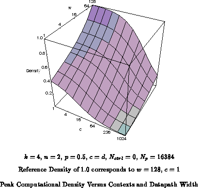
As the number of contexts, , increase, the device is supporting
more loaded instructions; that is, a larger on chip instruction diversity.
Figure
shows how instruction density increases with
increasing numbers of contexts alongside the decrease in peak computational
density.
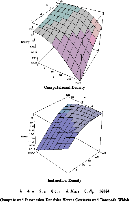
These same density trends hold if we set aside a fixed amount of data memory. The area outside of the data memory will follow the same density curves shown here.
As noted in the previous chapter, we can use larger granularity datapaths to reduce instruction overheads. The utility of this optimization depends heavily on the granularity of the data which needs to be processed. As noted in the previous section, the coarser the granularity the higher the peak performance. However, if the architectural granularity is larger than the task data granularity, portions of the device's computational power will go to waste.
We can model the effects of pure granularity mismatches using the
area model developed above. First, we note that the optimal configuration
for a given word size will always be the architecture which has the
same word size as the task. We can then determine the efficiency
associated with running tasks with word size on an architecture with
word size
, by dividing the area required to support the task on
a
architecture
by the area required on a
architecture. For
, for some integer
, the efficiency is simply the ratio of
the bit processing element areas. For
, the task can run
on top of the low
bit processing elements in the architecture
datapath, leaving the remaining processing elements unused. The
efficiency here is the ratio of the area of
bit processing
elements from a
architecture versus
bit processing
elements from a
architecture.
Note that a single-chip implementation is assumed for comparison so that there are no boundary effects between components.
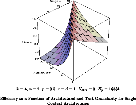
Figure shows the efficiency for various architecture
and task granularities. At
, the active switching area dominates.
The fine granularity (
) has the most robust efficiency across task
granularities. The efficiency drops off quickly for large grain
architectures supporting fine grain tasks.
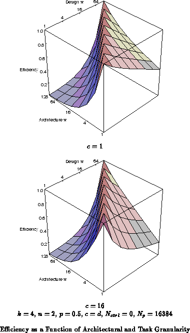
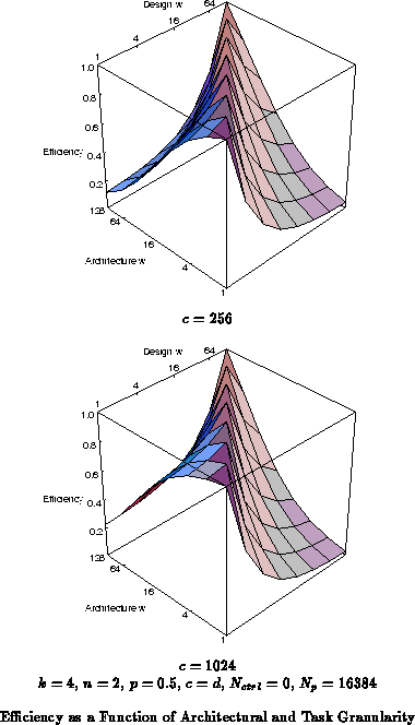
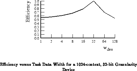
Figure shows that the robustness shifts as the
numbers of contexts increases. For
, the instruction memory space
dominates the area. Consequently, the redundancy which arises when
fine-grained architectures run coarse-grain tasks is quite large, leading
to rapidly decreasing efficiency with increasing task grain size. In this
regime, the coarse-grain architectures are more robust, since the extra
datapath and networking elements are moderately inexpensive compared to the
large area dedicated to instruction memory. For
,
, is the
most robust datapath width as shown extracted in
Figure
.
These robust points correspond to the mix where the context memory makes up roughly half the area of the device.
At this point:
We saw in Section that the computational density
is heavily dependent on the number of instruction contexts supported.
Architectures which support substantially more contexts than required by
the application, allow a large amount of silicon area dedicated to
instruction memory to go unused. Architectures which support too few
contexts will leave active computing and switching resources idle waiting
for the time when they are needed.
We can model the effects of varying application requirements and
architectural support in an ideal setting using the area model. We assume
we have a repetitive task requiring operations which has a path
length
. In an ideal packing, an architecture with
processing units and
instruction
contexts can support the task optimally. If
, the area per
processing element is larger than necessary to support the application. If
, it will be necessary to use more processing elements simply
to hold the total set of instructions.
This relation is shown for several datapath widths, , in
Figure
. Again, single chip implementations are assumed for
comparison.
The efficiency dropoff for is less severe for large
datapaths, large
, than for small datapaths. Similarly, the dropoff for
is less severe for small datapaths than for large datapaths.
This effect is due to the relative area contributed by instructions.
In the small
case, the instruction area takes up relatively more area
than in the large
case, so costs of extra active area is relatively
smaller than in the large
case. In the large datapath case, the
instructions make up a lower percentage of the area so the overhead for
extra instructions is relatively smaller.
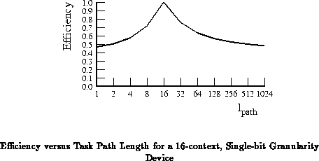
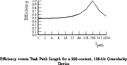
The 16 instruction context case is the most robust across
this range for single bit datapaths (See Figure ).
Similarly, 256 instruction contexts is the most robust for
(See Figure
). Neither of these cases drops much
below 50% efficiency at either the
or
extremes.
These ``robust'' cases correspond to the points where the instruction
memory area is roughly equal to the active network and computing area.
In either extreme, at most half of the resources are being underutilized.
, our robust context selection, can be defined as:
Remember that the network resource requirements grow with array size. In
the case, where we must deploy more processing elements to
handle the task, the total number of processing elements increases causing
the switching area per processing element to increase as well.
This effects acounts for the fact that the efficiency can
drop below 50% and the approximate relation in Equation
.
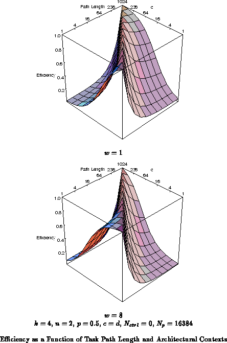
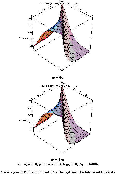
In general, we see cumulative effects of the grain size and
context depth mismatches between architecture and task requirements.
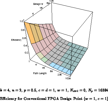
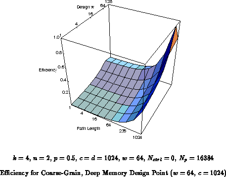
Figure shows the yielded efficiency versus both
application path length and grain size for the conventional FPGA design
point of a single context and a single bit datapath. The FPGA drops to
1% efficiency for large datapaths with long path lengths. Similarly,
Figure
shows the efficiency of a wide word
(
), deep memory (
) design point. While this does well for
large path lengths and wide data, its efficiency at a path length and data
size of one is 0.5%. Notice here, that the wide, coarse-grain design
point is over 100
less efficient than the
FPGA when running tasks whose requirements match the FPGA, and the FPGA is
100
less efficient than said point when running tasks with
coarse-grain data and deep path lengths.
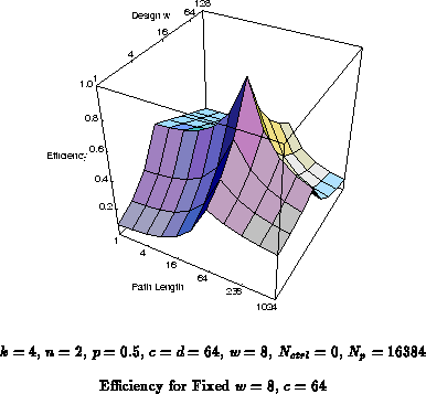
In the previous sections we saw that it was possible to select reasonably robust choices for datapath width or number of instruction contexts given that the other parameter was fixed. We also saw that the robustness criterion followed the same form; that is, the inefficiency overhead can be bounded near 50% if half of the area is dedicated to instruction memory and half to active computing resources. This does not, however, yield a single point optimum since the partitioning of the instructions between more contexts and finer-grain control is handled distinctly in the two cases.
Figure , for instance, shows the yield for a
single design point,
,
, across varying task path lengths and
datapath requirements. While the
and
cross-sections are
moderately robust, the efficiencies at the extremas are low. At
,
, the efficiency is just under 8%, and at the
,
, the efficiency is just over 8%. This design
point is, nonetheless, more robust across the whole space than either of
the architectures shown in Figures
and
.
The area model shows us how peak capacity depends on granularity
organization and instruction support. We see that the penalty for
fine-granularity is moderate, 2.5 difference between
and
, in the configurable domain where there is only instruction memory
for a single context. The penalty is large, 36
, in the heavy
multicontext domain. We also looked at the effects of application
granularity and path length. In both cases, we found that, given a
priori knowledge of either the task granularity or context requirements,
we could set the other parameter such that the efficiency did not drop
significantly below 50% for any choice of the unknown parameter. This is
significant since the peak performance densities across the range explored
differed by roughly a factor of 200
. For both of these cases, the
robust selection criterion is to choose the free parameter such that
instruction memory accounts for one half of the processing cell area. We
saw that the effects of granularity and path length mismatches were
cumulative and that FPGAs running tasks suited for deep memory,
coarse-grained architectures can be only 1% efficient. If we must select
both the datapath granularity and the number of contexts obliviously, we
cannot obtain a single design point with as robust a behavior as when we
only had one free parameter. A good design point across this region
of the RP-space suffers a 13
worst-case overhead.