NIACT-ORBIT Data Sheet
Andre DeHon
Original Issue: August 1993
Last Updated: Fri Nov 5 13:26:44 EST 1993

NIACT-ORBIT is an implementation of METRO LINK (tn75) specialized to serve as a net-in. NIACT-ORBIT was fabricated in a gate-array technology by Orbit Semiconductor. NIACT-ORBIT serves to transport data from a METRO (tn73) network to an MBTA processing node and memory (tn38). Serving as a net-in, NIACT-ORBIT connects to a network output port and can receive messages for an MBTA node.
NIACT-ORBIT handles virtually all of the necessary low-level issues of message reception including remote memory references, node reset, and remote operation queueing. It is intended to handle the portions of the network interface which must be implemented in hardware and are well understood now. NIACT-ORBIT handles:
NIACT-ORBIT was compiled with the METRO LINK configuration
bit NI set to one. It supports an 8-bit wide data path.
Additionally, to more robustly interface with networks constructed from
cascaded, 4-bit METRO routing components, it has two separate forward
and backward control bits allowing point-to-point port connections between
NIACT-ORBIT and its attached METRO network. On the node side,
NIACT-ORBIT supports a four-slot, 64-bit pipelined bus clocked at
one-half the network speed. Processor NIACT-ORBIT
communications are support during designated processor cycles using the low
32-bits of the 64-bit node datapath.
The second scan path ( TCK<1>, TMS<1>, TDI<1>, TDO<1>, TRST_L<1>) is a placeholder for future revisions which may support two scan paths. TDI<1> is connected directly to TDO<1> and the other signals are unused.
RETRANS is not used by the NIACT component, but is retained for uniforimity with the NOACT design. Similarly, NIACT does not use RND_IN.
NIACT-ORBIT requires 151 signal pins. Packaged in a 208-pin PQFP
package, NIACT-ORBIT 57 power and ground pins (29 ground, 28 VCC).
Figure shows the assignment of signal pins to package
pins.
The pins function as follows:
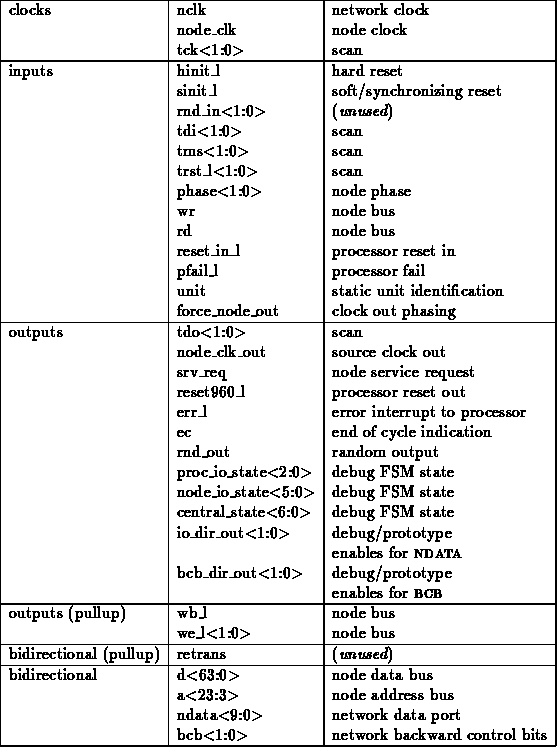
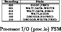
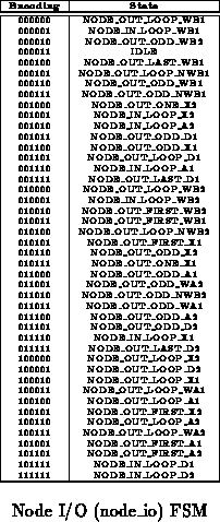
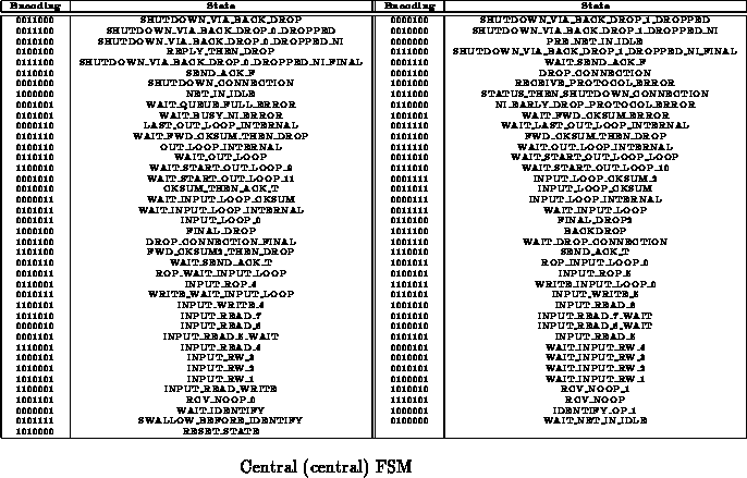
For purposes of debugging, the state bits from the three main
finite-state machines inside NIACT-ORBIT are available on output
pins. Section details the symbolic-state encodings
used by NIACT-ORBIT for these finite-state machines.
The enable signals associated with the bidirectional network lines are available as outputs. Since these enable signals are available outside the component, an unintelligent level-translator can serve to connect NIACT-ORBIT up to network components which do not use CMOS level signalling.
NIACT uses NCLK to time synchronous communications with the network and NODE_CLK to time synchronous communications with the node. NODE_CLK should run at half the frequency of NCLK. (tn36) describes how METRO LINK bridges the gap between these two clocks and details the requisite NCLK- NODE_CLK phase relationship. NODE_CLK_OUT is a div-2 clock signal generated from NCLK and is suitably timed to serve as NODE_CLK or as a reference clock source for the generation of NODE_CLK. If buffering introduces sufficiently small delay (See (tn36)) and skew, NODE_CLK_OUT can be buffered to generate NODE_CLK. In high-performance systems, it will probably be necessary to use a PLL clock buffer/generator and use NODE_CLK_OUT from one of the METRO LINK components on the node as the reference clock.
NIACT-ORBIT has a single, functional TAP for configuration. It
supports one non-bypass registers on the data scan path, and hence one
non-bypass instruction. Table summarizes all the scan
registers. The scan configuration register must be loaded with
meaningful values in order for the component to perform properly.
Configuration registers will retain their values across chip reset, but
will not retain their values when the chip is powered down.

When an instruction-shift is initiated through NIACT-ORBIT, the router will place the value 0b10101001 onto the scan path to comply with the IEEE TAP specification and to serve as an ad hoc component identification.
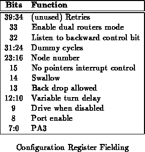
Figure shows how the various METRO
LINK configuration values are arranged in NIACT-ORBIT's
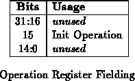
configuration register. The values labelled ``unused'' exist in the
configuration register for uniformity with NOACT-ORBIT (tn91),
but their values have no effect on NIACT-ORBIT. The significance and
interaction of these configuration options is detailed in (tn75).
For NIACT-ORBIT A<12>=0 all control register read/write operations. All reads with A<12>=1 will return the pointer currently at the head of the incoming message queue -- i.e. The address where the next remote operation request will be queued. None of the address bits above bit 12 affect read or write operations to NIACT-ORBIT.
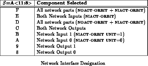
All the METRO LINK network interfaces on a node share the same
address bus and nodenetwork control signals. The
components use bits 11:8 of the address bus to determine which component
should respond to each network read or write operation.
Table
summarizes the encodings.
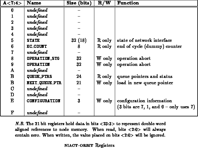
Bits 7:4 select the register addressed by each read or write operation
to which a given NIACT-ORBIT responds. Table
summarizes the registers and their encodings. (tn81) and
(tn75) explain how these registers are used by each METRO LINK
component.
Writes to OPERATION and OPERATION_STG can be used to abort ongoing message reception on NIACT-ORBIT. The remaining bits in the operation register are reserved for uniformity with NOACT-ORBIT.
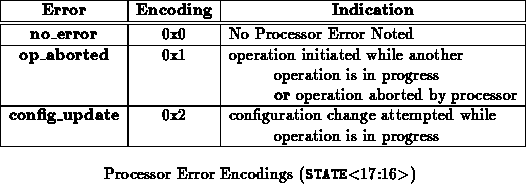
The STATE register contains data which indicates the status of
NIACT-ORBIT including the current disposition of the most recently
requested message launch. Table shows the fielding of
data in this register. Table
shows how to
interpret the processor error field.

The processor accessible configuration register contains the processor
error clear bit. Table shows the placement of the
one active configuration bit in the configuration register. When set,
bit 7 tells NIACT-ORBIT to clear its error interrupt signal. The
signal is cleared the whole time this bit is set, so it should be reset to
zero after being cleared if the processor wishes to receive notification
of any further errors.

Table summarizes the encodings for the primitive operations
supported by NIACT-ORBIT. All other operation encodings are treated
as user-defined, remote function invocations. (tn81) and
(tn75) detail the behavior of these operations. These operation
encodings can be seen in the STATE register (See
Table
) during operation reception.

When remote function invocation requests arrive at a network input MLINK, the incoming message is stored away in a buffer in memory. The address of the buffer is taken from the front of the receiving MLINK's buffer address queue. Each network input keeps its own address queue of buffers for incoming messages. The processor is responsible for adding addresses to these queues when they run short.
The processor can add an entry to a network inputs address queue by
writing the address to the NEXT_QUEUE_PTR address. The two
NIACT-ORBIT's on each node do not coordinate on queue maintenance, so
the queue pointers should be unique between the two network interfaces.
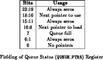
The processor can check the status of a network input's queue by reading
the QUEUE_PTRS address on the network input. The value read
contains the current value of the head and tail pointers of the queue and
status bits indicating when the queue is full or depleted (See
Table ). In NIACT-ORBIT, the queues can hold up to
seven entries. When the tail entry is 7 greater (mod 8) than the head
entry, the queue is full. When the entries are equal, the no-pointers bit
is set and the queue is empty. The tail pointer is automatically
incremented when a new value is written to the NEXT_QUEUE_PTR
address. The head pointer is incremented after MLINK finishes
writing an uncorrupted remote function request into the buffer specified by
the head pointer. The processor should use the current value of the head
pointer to determine which buffers have been filled with incoming message
data and are ready for processing.
The data stored in the buffer is formatted as shown in
Figure . The first word is composed from the remote
address and the configured high byte (PA3 -- See
Section
). This word should be directly usable as an
address to invoke the remote function handler. The second word is composed
from the operation identification and the data length. The third and
following words are the data which was sent along with the message. Data
words appear sequentially in the same order they appeared in the outgoing
memory buffer as sent by NOACT-ORBIT.
NIACT-ORBIT uses the encodings in Table to
communicate with a METRO network. In dual router mode,
NIACT-ORBIT provides separate control bits for each nibble of the
8-bit-wide data word. Bit <10> (<11:10>) is the backward control
bit used for fast-path reclamation. When this line is asserted (high), the
downstream router (or NOACT-ORBIT) is requesting that the connection
be collapsed.
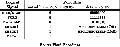
Each data transmission through the network is guarded by a 16-bit CRC
checksum. This checksum is initialized with the node number for the
destination node and updated with each byte of the message between the
beginning of the message and the first byte of the checksum. CHECK1
contains the bottom byte of the checksum and CHECK2 the top byte.
The CRC checksum is computed using the CCITT 16-bit checksum polynomial
[Int86] shown in Equation .
Checksum generation and verification is fully compatible with NOACT-ORBIT.
For potential debugging and statistics gathering purposes,
NIACT-ORBIT makes the state bits for its three major finite-state machines
available on package pins. The encodings for these states are summarized
in Tables ,
,
and
. Refer to the source design data for the meaning
of these states.
NIACT-ORBIT is configured for operation in three parts:
NIACT-ORBIT comprised approximately 20,000 gate-array gates and was fabricated on Orbit's base-array with 30K gates.
To Be Determined --
NOACT-ORBIT [DeH93c] and NIACT-ORBIT have been designed to work with METROJR-ORBIT (tn90) to link processing nodes up to METRO style networks. Both NIACT-ORBIT and NOACT-ORBIT have an 8-bit network datapath. Using METROJR-ORBIT's width-cascading feature, a suitable network may be composed from pairs of METROJR-ORBIT routing components. In the dual-routers mode, the ports from NIACT-ORBIT and NOACT-ORBIT are designed to attach directly to such a cascaded network.
