METRO LINK
METRO Network Interface
Andre DeHon
Original Issue: September 1992
Last Updated: Fri Nov 5 13:33:34 EST 1993

METRO LINK ( MLINK for short) provides an interface between a METRO based network and the processor and memory on an MBTA node. The core unit for MLINK can be configured either as a network input ( net-in), dealing with all network traffic destined for the node, or as a network output ( net-out), dealing with traffic originating from the node. This note describes the function and behavior of MLINK
METRO LINK is designed to handle several primitive operations directly without need for intervention from the processor. For more complicated operation, it simply serves as an interface between the processor and network, acting under the direct control of the processor.
MLINK handles virtually all of the necessary low-level issues of communication. It is intended to handle the portions of the network interface which must be implemented in hardware and are well understood now. The network interface is especially intended to handle operations which need to be implemented efficiently in hardware in order to obtain a reasonable level of performance. To this end, the network interface handles:
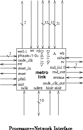
The network interface component is shown in Figure .
(tn25) shows how network interfaces are integrated into an MBTA node.
Table
describes the network interface's data and control
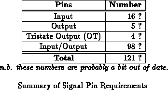
signals. Table
summarizes the pin requirements for this
component.
The network interface component needs to be synchronized to both the network and the node. To keep the frequency of the node in line with that of the network, the network interface provides NODE_CLK_OUT which is used as the source for clocking the node. NODE_CLK_OUT runs at half the frequency of the network clock ( NCLK). To avoid skew problems with the node, the signals which interface with the node are synchronized to the input clock, NODE_CLK, which is presumed to be result of buffering NODE_CLK_OUT so it can be fanned out to all components on the node requiring clocks. See (tn37) for further details on MBTA clocking strategy.
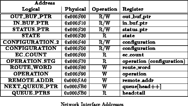
The processor communicates with each network interface as a memory
mapped device. Table shows the relevant communication
offset addresses within each network interface's designated memory region.
Each network interface has its own memory region assigned by the node bus
controller (tn30). Bits 7:4 of the address are used to distinguish
which network interface is being addressed. W and R are used
to indicate active processor address cycles intended for the network
interfaces. All communications directly between the processor and a network
interface takes place on the low data bus (D<31:0>); as such all
network interface addresses are at least double word aligned.
The processor will only address the network interface during the processor's designated memory cycle. The processor will never communicate with a network interface during a borrowed memory cycle.
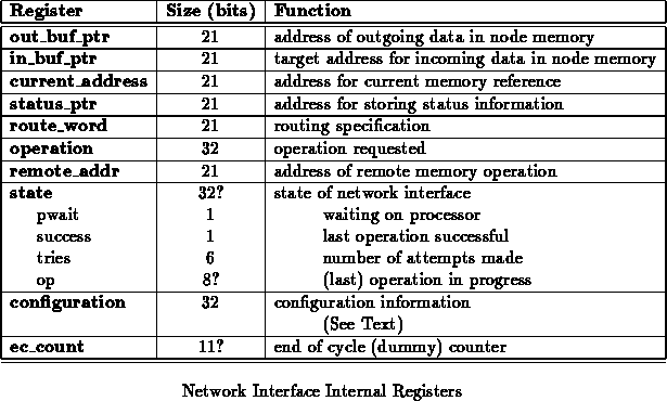
Table lists the internal registers in the network
interface. Many of these can be read or changed through addresses shown in
Table
. Each register is described elsewhere in this
document where its function is relevant.
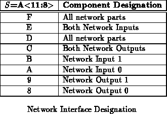
Note that Table marks the 3rd lowest nibble (bits 11:8)
as
. These bits specify which network part is being addressed by the
memory operation. Table
summarizes the meanings of the
various values of
.
The network interface uses the node's SRAM for the source and
destination of data sent over the network. The processor tells the network
interface where to put incoming data for a remote handler invocation
network operation or from a remote read by setting the
out_buf_ptr. Similarly, the processor tells the
network interface where to find outgoing data by setting the interface's
in_buf_ptr. Once set, these pointers remain in effect until
changed. As such, it is only necessary for the processor to respecify a
pointer when a target memory location changes. These pointers should not
be changed while the network interface is performing an operation which
uses them to reference memory.
The remote_address register specifies the destination address on the remote node for raw write operations. This register is only used when the interface is configured as a network output and performing a network write operation or remote handler invocation.
The actual values used for setting up a route through the network are
specified by the route-word. MLINK sends the bottom one to four
words of the route-word into the network at the head of the message as
configured in the configuration register (Section ).
The routing specification will be highly dependent on the details of the routers being used, their configuration, and the topology of the network. By allowing the node to specify the routing word entirely, this information does not need to be hardcoded into the network interface. This allows a single METRO LINK design to service a wider range of METRO implementation and network topologies.
The node may want to use a lookup table to map from destination
addresses to routing specifications. Another option is to generate the routing specification
when the destination is determined and store it with the appropriate
data-structures so it is readily available when needed.
Note that the DST specification in the operation
(Section ) is only used to verify that the
message ended up at the right place -- and does not affect the route
selected through the network.
The processor tells the network interface to perform an operation by writing to the OPERATION or OPERATION_STG address. All transactions are initiated or aborted by issuing an operation.
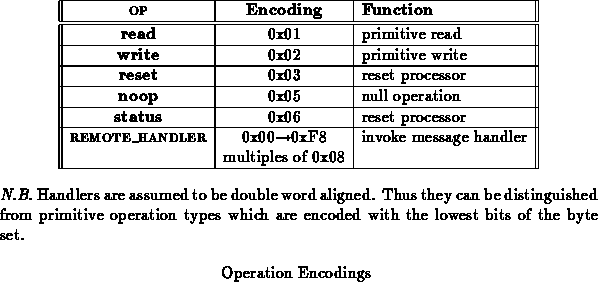
The general format of an operation is:
LEN OP
FUNCTION
DST
Each portion of the operation word is one byte in length. DST specifies the destination node for the specified operation. LEN specifies the length in double words of the operation. OP specifies the operation to be performed at the remote node when a primitive operation is being performed. FUNCTION specifies whether to initiate or abort an operation. Additionally, when the OPERATION_STG address is used to initiate an operation, number of route word and number of registers portion of the configuration register are reloaded. This allows MLINK to function effeciently in the case where all paths through the network are not the same length and may contain varying number of routers in each path.
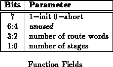
Figure shows the interpretation of the bits within the
FUNCTION byte. The highest bit is used to decide whether to start or
abort an operation.
As described above, the lower four bits are only loaded when the
OPERATION_STG address is used. These values are loaded into the same
register as the corresponding fields in the configuration register and will
hence superceede anything previously written using the configuration address.
ABORT instructs MLINK to drop the current operation and return to its idle state as soon as possible. When in transmit mode, MLINK will drop the connection immediately by send a DROP and returning to idle. When receiving, if the BCB is active, MLINK will use BCB to attempt to get the connection shutdown and return to idle as soon as transmission stops.
LEN specifies the length in double words of data to be transferred during a network operation. This is required for all operations. For operations which transfer a fixed amount of data ( i.e. noop, reset, status), it should be consistent with the amount of data expected.
DST specifies the intended destination node for the network message.
Note that this is needed to guard against incorrect delivery rather than to
specify a route through the network. The routing word
(Section ) will be used for the actual route through the
network.
this text/details need to be updated to reflect: (1) two configuratin registers, (2) new selection paramters incl. rnd/deterministic selection...
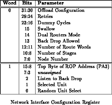
The network interface has a number of configurable options. It is possible
to specify the number of dummy cycles between real network data by setting
dummy-cycles. The number of retransmissions net-out will attempt is
specified by retries. The number of network stages can be selected
by setting stages. The node number is configured by setting
node-number. Figure
shows the composition of the
configuration register. Individual portions of the word cannot be set
independently. To change just part of the configuration, read the
configuration, reset the desired bits, and write the configuration back.
The unused bits in the configuration word are available for other
configuration options which may come up during design and prototyping.
Space is specifically left next to the number of dummy cycles so this
parameter can be expanded if early experience with MBTA indicates the
number of allocated bits is insufficient.
this paragraph is incomplete -- it will get updated later when things
settle down -- See Figure
.
N.B. These things will most likely be loadable under boundary scan control in the future.
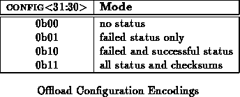
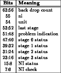
The status_ptr points to the memory location for the status buffer. Net-out will place the result of each network retransmission in successive double words in memory starting at the address stored in status_ptr. The status_ptr has no use when the interface is configured as a network input. For each failed network attempt, one double-word is written to memory.
Each time a connection is attempted, the status word is updated. When a connection fails and MLINK is configured to offload error status, the status word will be written out at the current status pointer. The status pointer is incremented with each trial so that the connection attempt history is available after the connection is made or MLINK gives up on attempting the connection. When a connection is successfully opened, the status word will be written out if configured to do so by offload successful status. Any operation which turns the turns the network more than once from the forward direction will only store the status from the final turn -- connection-wise, this data should be identical to that acquired on the first turn ( will we actually have any of these?).
this may be a bit out of date -- see tcf code and update
Some text describing this would probably be nice.
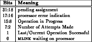
Reading STATE will return state information of the network interface. The format and meaning of this word will be defined as the component is implemented. Some subset of these bits should indicate what the interface is expecting from the processor. This may also be useful for keeping the processor in synch with the component. The state as a whole should be useful in diagnostic testing.
The state currently indicates the following:
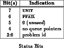
When errors occur such that the network interface is forced to signal the
processor that an error has occurred using its
line, the processor should be able to determine the error by reading STATE.
The current list of possible errors is shown in Table
.
N.B. All of the errors shown so far are essentially fatal. When one
of these errors occurs, either the processor and the network interface are
in inconsistent states or there is a bug in the source program. The
assertion of indicates that such an error has
occurred; the processor should halt and signal the error to the host so the
source of the error can be located and debugged. At present, there is
no way to turn
off, short of doing a hard
reset...we might want to rectify this.
Currently not noting pointer reloads while operations are in progress. We might want to set something up to monitor that, as well.
The state address can also be used to check the successful completion of an operation. As such it is used in two slightly different ways depending on the network operation performed. After any operation which turns the network around for an acknowledgment but not for data ( i.e. noop, reset, write, or remote handlers), it indicates whether or not the ack returned indicated the success or failure of the operation. After any operation which sends a response over the network ( i.e. read and status), it indicates whether or not the reply checksum was correct. The second lowest state bit indicates whether or not the ack or final checksum has been received. This bit is cleared at the beginning of an operation and is set when the ack arrives (actually, the final ack when retries are configured). The lowest bit is only valid when this second lowest bit is set. The lowest bit indicates the state of the actual success or failure of the operation. When set, the operation succeeded ( i.e. the ack was true or the checksum was valid); when cleared, the operation failed ( i.e. the ack was false or the checksum was invalid).
Each network interface will be counting the number of dummy cycles so it will know when to send and expect real data over the network. Each emulation cycle is composed of eight real network cycles and hence 8 sets of dummy cycles. The end of cycle counter keeps track of the number of dummy cycles and the real network cycles. Dummy cycles count from 0 modulo the configured number of dummy cycles plus one. The dummy cycle counter is incremented every node cycle. The phase counter counter increments every network cycle and counts from 0 modulo 8. Each reset of the phase counter denote a node cycle and hence increments the dummy counter. The end of cycle counter is formatted as:

The two network outputs used in an MBTA node function logically as a single network output interface which randomly selects between network ports for transmissions. RND_IN and RND_OUT are used to select the output port, and hence the associated net-out, for a particular transmission attempt
When the processor initiates a network transaction, it writes the operation generically to net-out. Both network outputs receive the operation. They both xor RND_IN and RND_OUT together. If the result of the xor is the same as the network interface's UNIT designation, the network interface handles the network transmission. In this manner, exactly one net-out attempts to transmit the network transaction.
If the previous attempt to open a connection fails, another attempt must be
made to open the connection. The network outputs need, once again, to
randomly select a network port. The net-out which made the failed
connection attempt, asserts to indicate that
retransmission is necessary. The other net-out does nothing except
wait for the next operation or retransmission. On the network cycle
following the assertion of
, both net-outs xor
RND_IN and RND_OUT together and select which network
output will handle the retransmission. The assertion of
also signals the idle net-out to increment its retries counter.
After receiving a TURN byte, net-in transmits STATUS
and CHECKSUM. mumble status see Table ;
mumble checksum.
mumble bit meanings
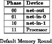
Each network interface has an opportunity to access memory once every
eight real network cycles. Since the memory is 64 bits wide, this is just
frequently enough to transfer data at the full network data rate when
necessary. During an eight network cycle memory round, each logical
network interface has a designated access cycle on each shared bus (
i.e. address and data busses). The portion of the round belonging to
each logical network interface is shown in Figure .
When a network interface wants to use memory during its access cycle, it
asserts the want bus ( WB) signal during its designated WB cycle prior to
presenting the data to be read or written. Along with asserting WB,
the network interface should assert the appropriate word write enables
(<1:0>). When writing to either or both words of the
specified memory location, the appropriate word write enable should be
asserted. For memory reads, both word write enable should be deasserted.
The host bus controller (tn30) deals with turning the WB and
<1:0> signals into the appropriate enables for the SRAM
memory. The network interface does not support byte writes. Both WB
and
<1:0> should be asserted only during the network
interface part's respective cycle on the write enable bus.
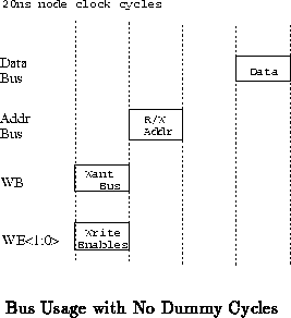
Node memory operation timing differs somewhat when there are no dummy
cycles from when there are dummy cycles. With no dummy cycles, the network
interface will generally be performing back to back memory cycles in the
pipelined fashion required by the node bus. Figure shows
what the bususe from a single network interface looks like. This pattern
of usage is repeats as necessary for each memory interaction. As mentioned
above each network interface has its own designated cycle for use of the
data and address busses so each network interface uses this pattern
appropriately out of phase with its peers. During the R/W Addr cycle
the address of the next read data or the previous write data is presented
(see (tn25)).
When dummy cycles are present, each network interface only references
memory during the beginning of the each emulation cycle. As such, it is
not possible to optimize back to back memory cycles. Instead, within the
two node cycles following the beginning of the cycle, each network
interface performs a complete read or write operation. The processor is
then free to steal cycles during the remained of the emulation cycle
knowing that the network interfaces will not require use of the node busses
until the beginning of the next emulation cycle. Figure
shows the end of cycle and bus timing when dummy cycles are present. As
noted, the point at which the EC signal is asserted with respect to
the phase of a network interface depends on the network interface.
For network-input 0 (which is
out of phase with the processor
and hence the only unit from which the processor will be stealing bus
cycles), EC is asserted during its designated address phase one
node cycle before the network input uses its address bus. This allows the
bus controller adequate warning so that the address bus will be available
if the network interface wishes to perform a read operation.
The bytes of a network message can be classified as follows:

The destination specifies the node in the network to which the network message is directed.
N.B. This limits the number of nodes to 256. This should not pose any long term limitation since we will certainly have revised many of these details (including going to a larger address space) by the time we build a machine with more than 256 nodes.
For read and write operations, there will be three bytes of address to specify the address of data on the remote node.

The data associated with each operation will be transmitted with each word broken into four byte chunks.
For operations of non-fixed size, a length byte specifies the number of consecutive memory words being transfered (or to be transfered).
Current issue: Should we allow operation of odd-word lengths? Its not clear if its worth the hair. Would we be hurt by the restriction to only multiples of double-word transfers?
The integrity of each network transaction is verified with a forward checksum [DeH90a]. The checksum is a 16-bit CRC checksum and is transmitted in two consecutive bytes ( CHKSUM1 and CHKSUM2) The forward checksum uses the same CRC checksum generator used by RN1B [Min91].
Some operations require no data in a response. Ack provides a
succeed/fail response to indicate the completion of such operations.
Ack is used generically to refer to responses which can be ack_t
or ack_f (see Table ).

Often, the node may not be able to respond immediately to a network operation. When the node cannot supply the requested data to the source immediately, it must be capable of telling the source to wait. To allow this specification, METRO includes a distinguished DATA-IDLE specification which keeps the connection open, but is out of band of the normal data stream so MLINK can tell that it is not to be treated as normal data. After an operation is requested, DATA-IDLE will be transmitted to the source until the destination node can field a reply. Once ready to reply, the destination node is ready to send data, it resumes by sending the reply data.
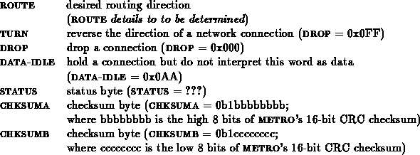
METRO defines the message components shown below. The ninth bit shown here is the control bit [EDP +92].
This section describes the format each network transactions using the components described in the previous sections.
Some things to note:
Following is a noop or reset operation sequence as seen from
the interface between the sending node and the network. denotes the
number of network stages.

This same sequence for a noop or reset operation looks like the following from the interface between the network and receiving node.
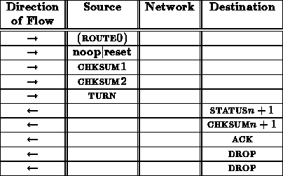
Note that the status checksum groups numbered 1 through come from
the successive routers in the network. The status/checksum pair labeled
comes from the network interface at the destination node.
See
for a description of these status and checksum bytes.
A noop and reset transaction should always succeed. Thus, the ACK should always be ACK_T.
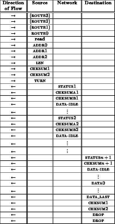
A read transaction proceeds as follows
From the interface between the network and receiving node, this read sequence looks like:
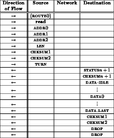
The final checksum is necessary to make certain that the return data arrived uncorrupted.
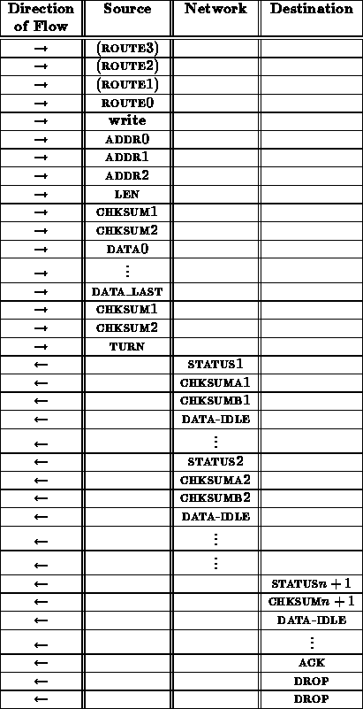
A write transaction proceeds as follows:
From the interface between the network and receiving node, this write sequence looks like:
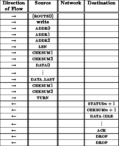
The ack here is necessary to provide a final opportunity for the receiving node to indicate that it was not able to deal with the write transaction and the operation should be repeated. This is important in the case where the data arrives corrupted.
It is necessary to specify the length ( LEN) of the data to be written in order to guarantee that faults in the network ( e.g. a control bit stuck asserted) do not cause a write operation to write over important data in the node's memory. A checksum is included immediately after the address and length specification to protect the receiving node's memory. This checksum comes before the data and is used to assure that the address and length have been received correctly before anything is overwritten in memory. This prevents transmission errors from overwriting random sections of a node's memory.
A status transaction proceeds as follows
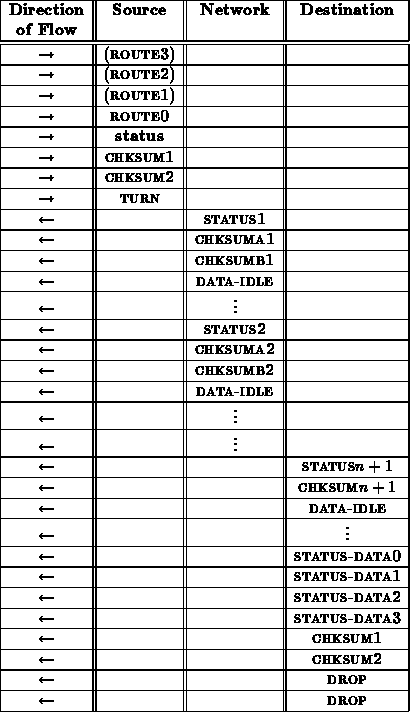
From the interface between the network and receiving node, this status sequence looks like:
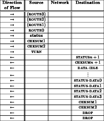
Exact content of status data is still being determined.
An remote handler invocation transaction proceeds as follows:
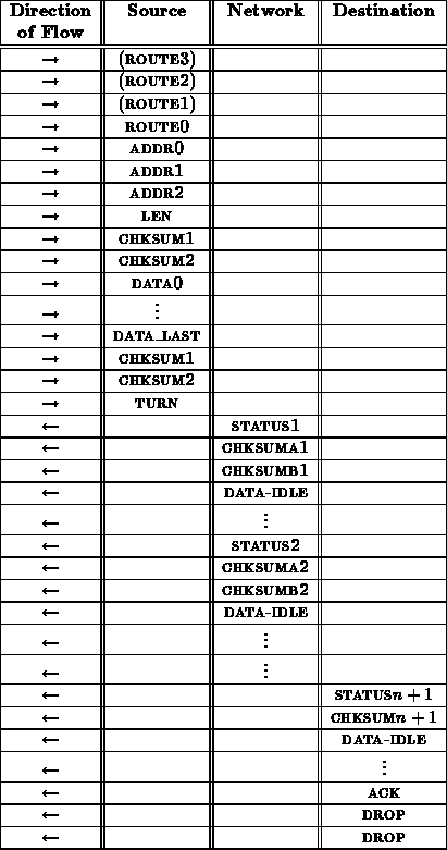
From the interface between the network and receiving node, this rop sequence looks like:
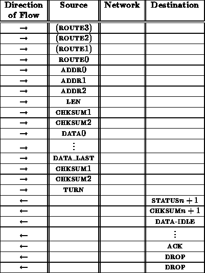
As in the case with the write operation, the inclusion of the CHKSUM following LEN is necessary to prevent faults from allowing MLINK to write over useful data in memory.
Exactly what happens after the turn is currently a subject of debate. In the past, we wanted to support holding the connection open for a reply as well as turning the network an arbitrary number of times. The utility and desireability of this is not clear at present. Comments welcomed.
In this section the following conventions will be used to distinguish required and optional processor operations:

It is always optional to specify new buffer pointers. Checking acknowledgments is never required, but always recommended.
All the sequences in this section concentrate on the i/o operations between the processor and the network interface. Intervening computation by the processor is categorically omitted.
Only network outputs will actually originate network operations. This section briefly describes the way the processor uses net-out to issue network transactions.
Checking the success of a network operation is not explicitly shown in the sequences which follow. In general, the processor will want to read the net-out's STATE to check on its progress and perhaps look at the status words in memory. When a network output fails to successfully open within the configured number of retires, the network output will cease to attempt retransmission. The processor should recognize this occurrence when it checks the state of the network output.
A noop or reset sequence proceeds as:
Following is a C-rendition of the above sequence using a busy-wait on the
acknowledgment:
In general, it would probably be more useful to store away a pointer to a handler to deal with the operation when it completes or fails and let the processor go on to doing something else rather than busy-waiting on the return ack as shown above.
A status sequence proceeds as:
A read sequence proceeds as:
A write sequence proceeds as:
A remote handler sequence proceeds as:
Many things still to be decided here.
When configured as a network input, the network interface will autonomously
handle all of the incoming low-level network transactions described in
section except remote handler invocation transaction
which implicitly requires the processor's control. (???)
These transactions require no node resources.
When a NOOP network transaction is received, net-in drops the
connection after returning its status and checksum bytes. See
Section for information on the status and checksum bytes.
When a RESET network transaction is received, net-in drops the
connection after releasing the signal on the node and
returning its status and checksum bytes.
Note that this transaction does not hang around to verify that the node
boots successfully. It is easy to arrange things such that once the node
is booted far enough to send messages under it's processor control, it can
send a reply back to the booting node. Additionally, the STATUS
message can be used to check if the processor's pin is
asserted.

Net-in can directly handle the raw memory transactions described in
(tn21). This along with the RESET transaction allow the node to
be booted over the network without EPROMs (tn19) [DeH90b]. The
node bandwidth is sufficient to handle these raw operations at the full
network data rate (see Section ). The format of data received
and transmitted over the network during any of these transactions is given
in
.
Upon receiving a read transaction, net-in returns the requested words at the emulation rate ( i.e. one word per emulation cycle). Following the last word, net-in sends a forward checksum on the data transmitted before closing the connection.
Write transactions are handled similar to read operations. One word is written into memory each emulation cycle. When the network is turned around following the transmission of the write data, net-in transmits an ack to indicate whether or not the write completed successfully. ack_f may occur for any of the following reasons:
On incoming write operations, the checksum on the address and length
fields of the message must be correct before net-in will write any
data to memory. This checksum is necessary to guarantee that random
portions of a node's memory are not trashed by transmission errors
(Section ).
In addition to autonomous transactions network inputs must handle remote handler invocations so the processor can respond accordingly.
The following is the way ROP's used to work in concept. This will probably change.
When an ROP is received, net-in places the contents of the
message in memory at the address specified by the out_buf_ptr.
The processor recognizes the arrival of the ROP by checking on the
state of net-in. Once received, net-in will hold the
connection open sending idle cycles over the network until the
processor sets up a response. During an ROP, the network can be
turned around as many times as the software requires. Once the initial
message is received, ROPs are handled in much the same way as
net-out handles ROPs (see Section ).
An ROP sequence proceeds as:
Here are some thoughts about checksums in the METRO / METRO LINK network.
This follows immediately from the fact that each router sees different routing bits. When we rotate the data to shift in new routing-bits, this makes the routers see different rotations of the data. When we swallow the head byte to get a fresh routing byte, the subsequent routers do not see the swallowed byte. Further, in tree machines [DeH91d], exactly what each router a given number of hops from the source sees will depend on the height of crossover in the trees.
To check the router checksums, one must compute a separate checksum for each router in the path from source to destination. Further, to check the checksums on the fly in hardware, this means one needs a separate checksum computation unit for each router in the worst-case path between source and destination.
From these observations, we conclude that the critical indication of success is the reply from the destination node. If the destination node accepts the message as complete and replies with a legal reply, then that is the authoritative indication of success. We do need to encode the reply so that it is sufficiently unlikely that a reply indicating failure can be corrupted into one indicating success.
The forward checksum is the most important checksum in terms of determining the success of message transmission.
The only think which the reverse checksums tell us is where in the network a message may have been corrupted. Further, this information is based on full-speed data transmission between network routers.
This allows us to move the checking of router checksums into software. Presumably, this would only be necessary in the rare cases when data is actually being corrupted. Moving it into software also allows any given METRO LINK to work with a larger range of networks since it is not necessary to code the data-permutations in effect for each router in the network into the network interface hardware. This also makes METRO LINK completely independent of the the checksum used by a particular router implementation. In fact, the router may have a mode where it transmits data back other than checksum information and METRO LINK will save it out in the same manner.
This section raises a number of recent/current issues. Many of these are unresolved and feedback is strongly encouraged.
What primitives should hardware support?
The current theory is that hardware supports the following:
These are probably minimally sufficient. There may be others which, if implemented in hardware directly, things would be much more efficient. However, at this point it is not clear what operations fall into this category. We have considered having some form of primitive read-modify-write operation, but the atomicity complications has us leaning to avoid actually handling such unless there are some very good reasons.
How are network messages/operations initiated?
As described so far, everything is done using some combination of writes to memory and writes directly to the network interface. For the most part, we believe the writes directly to the interface are not a problem. It might be inefficient for some messages to have to write the data out to memory first, then launch the operation. Thus, it might be worthwhile to be able to launch short messages directly from the network interface. This will, of course, require additional hardware resources on the network interface and there will have to be some limit on message sizes which can be handled this way. So there are many questions here:
What happens to operations when they arrive at the
destination?
Here, we are concerned primarily with remote function invocations.
How does the processor arrange to service incoming
messages (which need service)
This is related to the previous question.
What should we do with errors noted during
net-in message reception?
Unlike net-out since the net-in has no control over when it is busy, witting it out to memory is not really an option. Nor are successive messages to the same net-in necessarily related in any way.
Where should the destination MLINK's status be
returned?
Status is currently returned in the first byte of the pair returned by the MLINK. This requires that the forward checksum errors be noted and inserted into the outgoing status byte within one cycle. Now that the routers are not putting status in the first two bits of the first checksum word, it might make sense to rearrange so the status bits occur in the second checksum word.
Should we require all network ops to be double
word entities, or should we allow odd length read/write/handler-invocations?
I do not think we are willing to allow any transfers to odd word addresses, so this is only a question about length.
How long of a message should we support?
We currently support 256 Words. If we drop odd support, that could go to 256 double words = 512 words. Any additional length would require two length bytes be transmitted with each message instead of one (or some other restriction on the possible lengths).
Does the idempotence restriction limit what we can
express efficiently?
See [DeH92] for the issue and possibilities here.