Modular Bootstrapping Transit Architecture
Andre DeHon
Original Issue: April 1990
Last Updated: Tue Nov 9 12:48:49 EST 1993

The Modular Bootstrapping Transit Architecture (MBTA) is intended to provide a framework in which to study and experiment with the various components necessary for a large scale parallel computer. MBTA will be a parallel computer in its own right, but will be designed primarily as a testing ground for ideas. Built around a Transit network, the processing nodes are implemented from standard hardware. Nodes can be configured through software to emulate the ideas and systems under study. MBTA will allow an experimenter to test his ideas in a real parallel system without requiring him to build his own scaffolding.
Building a large scale parallel computer is a huge task. There is a considerable amount which we don't understand about how to build and program efficient parallel computers. There continues to be a chicken and egg problem in parallel system development. There remain only a small number of parallel applications and these are generally oriented toward a particular architecture. This dearth makes it hard to get a feel for the general behavior of programs in general parallel computational environments. The hardware is hard to design without the software to study, and the software is generally meaningless without a target architecture. We are left with a bootstrapping problem. We must begin to design, construct, and test hardware to provide an initial target for software development and paradigms. We must begin to study and code parallel computation in order to understand the desired hardware components.
MBTA attempts to provide a modular framework in which this bootstrapping can take place. Architecture and protocol ideas can be soft coded onto the machine. MBTA can then be used to emulate the system under study. Software can be targeted at the emulated system. Efforts at all levels of software, architecture, protocols, and paradigms can feed back on each other to fuel the bootstrapping processes.
The modularity provided allows experimenters to develop or experiment with one component of the system independent from others. The MBTA scaffolding allows the system component under study to be examined in the context of an operational machine. Variants of system components can be mixed and matched in order to study their interaction. As the pieces of the system are better understood, designs can be spawned off which replace the generic MBTA modules with hardwired components. The modular architecture should allow the rapid incorporation of such developments into complete parallel computer systems.
Why not just simulate everything in software?
Certainly, one might make a case for simulating the entire parallel system in software. This has the advantage of being even more configurable with a significantly smaller cost. I will deal with this alternative on several grounds.
Whereas its unclear the amount of parallelism of which we will be able to take
advantage in general, it is clear we can gain an speedup by
emulating an
processor parallel computer on
processors. In fact,
we should be able to get greater than a factor of
speedup on
in the hardware emulation. In a serial simulation, we must simulate each
component of the network in serial. In a parallel emulation, we need only
simulate the behavior of a single functional unit in serial. Each
functional unit will be able to perform its simulation in parallel.
E.g. Let us consider a simple system with a processor,
cache-controller, and memory at each node or endpoint. These endpoints are
then interconnected with a routing network. A serial simulation would have
to run the simulation of processors,
cache-controllers, and
routing components in serial. The hardware emulation will be able to run
the network, cache-controller emulation, and processor emulation
simultaneously.
Despite all good intentions, it is quite easy to unknowingly make assumptions in a software simulation which are unreasonable in a real parallel machine. Using a hardware emulation, many of these assumptions will become clear and one is forced to deal with them. In all likelihood many behavioral assumptions will still be made in emulations, but these will tend to be much closer to the behavior in the real machine.
We must still pay some attention to how the emulation is constructed and used to make sure it will honestly reflect the performance of a real parallel machine. As Prof. Dally pointed out [Dal90] if the software emulation of one component runs 10 times slower than one would expect in a real machine, while another runs at full speed, it would be possible to delude yourself about the performance of the machine when both run at full speed.
This issue will be addressed further in Section .
One validly could argue that constructing a fully generic configurable multiprocessor test frame would be a mammoth task itself. Additionally, it would certainly require considerable overhead to offer such generality and would be extremely expensive to implement.
MBTA is not intended to be a fully generic. The space of possible multiprocessor computers is quite large. Rather than trying to offer this full generality, MBTA is designed to emulate a certain class of machines which we consider interesting.
Using a transit network [Kni89] [DeH90b], we
target indirect network multiprocessor computers rather than direct network
machines. Section describes the transit network in more
detail. The configuration of the processor, memory system, and i/o
components were impacted by some of our gross ideas as to how an endpoint
should be organized. See Section
for a further details.
There is actually a second reason for implementing MBTA in this manner. MBTA will provide the framework to fully test and debug the transit routing network.
The MBTA hardware should be sufficient to allow moderate speed testing
of an assembled transit network. We don't expect the software emulations
to be capable of feeding the network at its capability. The raw hardware,
however, should be able to come close to pacing the network. As such,
carefully coded software should allow us to
test the functionality of the network at clock rates approaching the
capability of the network. This configuration will also allow us to
run simple performance tests on the actual network and gather meaningful
statistics.
The transit packaging scheme [Kni89] is somewhat novel. It still needs to be tested in full operation. Building MBTA with at least the network packaged in the manner will give us further experience with this packaging. We will have the opportunity to find and work out unexpected bugs in the scheme. MBTA will provide a realistic field test of this scheme.
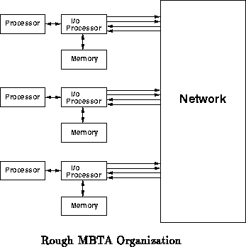
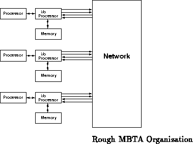
MBTA will be organized as some number of endpoint nodes interconnected with
a common network. The Transit multistage routing network (see
Section ) will be used for the interconnection network.
Conceptually, each endpoint will be configured to act as some sort of
computation processor, i/o processor(s), memory, and any other functional
blocks which seem appropriate for experimentation. The actual node
architecture is intended to be simple and generic so it can emulate the
wide variety of node architectures one might wish to study (see
Section
). Figure
shows the rough
organization of what an emulated multiprocessor might look like.
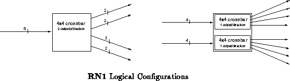
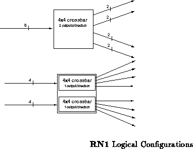
The routing component, RN1, forms the heart of the Transit network.
RN1 is a custom CMOS routing component currently under construction
to provide simple high speed switching for fault tolerant networks. RN1
has eight nine-bit wide input channels and eight nine-bit wide output
channels. These nine-bit wide channels provide byte wide data transfer
with the ninth bit serving as a signal for the beginning and end of
transmissions. RN1 can be configured in one of two ways as shown in
Figure . RN1's primary configuration is as a
crossbar router with a dilation of two. In
this configuration, all 8 input channels are logically equivalent.
Alternately, RN1 can be configured as a pair of
crossbars, each
with 4 logically equivalent inputs and a dilation of one.
Simple routing is performed by using the first two bits of a transmission to indicate the the desired output destination. If an output in the desired direction is available, the data transmission is routed to one such output. Otherwise, the data is ignored. In either case, when the transmission completes, RN1 informs the sender of the connection status so that the sender will know whether or not it is necessary to retry the transmission. When both outputs in the desired output direction are available, RN1 randomly chooses which port to use.
To allow rapid responses to network requests, RN1 allows connections opened over the network to be turned around; that is, the direction of the connection can be reversed allowing data to flow back from the destination to the source processor. The ability to turn a network connection around allows a processor requesting data to get its response quickly without requiring the processor it is communicating with to open a separate connection through the network.
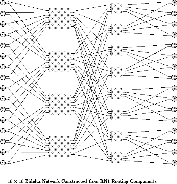
RN1 can be used to construct multipath bidelta routing networks
([KS86] [KS83]) or fat-tree routing networks
([DeH90b]). Initially, MBTA will use a bidelta style routing
network based around RN1. Figure shows a
bidelta style network constructed from the RN1 routing component. A single
physical RN1 routing component would implement two of the
crossbars in the second and final routing stage. To demonstrate the
multipath nature of this network, the wires available for routing a
connection from processor 6 to processor 16 are highlighted in
Figure
.
Future versions of MBTA may be constructed with the network arranged in a fat-tree configuration [DeH90b] [DeH90k].
RN1 is described further in [Kni89] and [Min90]. The fault tolerant characteristics of this style of multipath network is described in [DKM90].
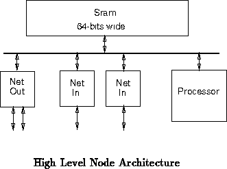
Each MBTA endpoint will be composed of a processor, memory, bus
logic, and network interfaces. Figure shows the high level
composition and organization of an MBTA node. This node architecture is
intended to allow both fast network testing and fair emulation [DS90a].
[DS90b] describes the alternatives and considerations which led to this
architecture. [DS90a] describes the node architecture in further
detail.
One processor design we are considering seriously will support:
With this in mind, the MBTA processor should be able to efficiently emulate this kind of processor. As such we will almost certainly need floating point capability. A 64-bit processor might be desirable; but in any case, efficient manipulation of 64-bit quantities is a necessity. Multiple register sets will be nice for efficient context emulation.
Also under consideration is a dedicated memory processor which is responsible for dealing with memory, cache, and network interactions so that the computational processor is free to deal primarily with computation.
We expect that this processor will perform the following tasks:
The load on this processor may be quite high. It might also be worthwhile to consider partitioning the memory management tasks so that two i/o processors can be utilized.
The node processor will emulate virtually all of the hardware one might
place on a node in the emulated computer. We have decided to use Intel's
80960CB to serve in this capacity (see [DeH90i] for other
considerations). A back-end compiler can compile instructions in the
target node's architecture into instructions understood by the 80960.
Alternately, the processor may decode and interpret instructions to
some extent as it executes. Compilation to the processor's instruction set
will probably provide faster emulation. Additionally, compilation will
probably have less extraneous memory requirements ( i.e. memory
requirements that are peculiar to the emulation and would not be incurred
with the actual processor being emulated). Compilation, however, will
generate much larger code, so some intermediate tradeoff may need to be
reached.
A mechanism should be provided to mark or count the number of virtual instructions executed. This will allow instruction execution to be normalized to the emulated processor. It will also provide a metric for evaluating the performance of the processor being emulated.
The physical memory will be a fast, flat static RAM memory. This will simplify node design and allow us maximum flexibility in software to emulate various memory configurations.
The emulated memory will be implemented on top of this fast static memory. This will probably be conceptually divided into regions such as:
For simplicity, no secondary storage will be included in the initial MBTA development. However, MBTA should be designed such that a future version could easily incorporate secondary storage.
To interface properly with RN1, some hardware will be necessary to convert memory transactions into network packets and vice-versa. The high-level control of these operations will be the responsibility of the MBTA processor, and hence easily reprogrammable. The network interface hardware will deal with the lower-level, speed-critical, portions of this interface, including:
This interface will be implemented with a network interface component [DeH90g]. Two such network interface components will handle outgoing network traffic while two handle incomming network traffic for each node.
MBTA's configurability is provided in the ability to program the behavior of the compute and i/o processor. This should allow considerable freedom to study issues like processor architecture, caching schemes, coherence protocols, garbage collection schemes, network protocols. Additionally, some freedom should be available to experiment with the partitioning of these tasks among the processing resources.
At the lowest level, the experimenter has complete control to code the behavior of the compute and i/o processors. It might be interesting to develop some higher level interfaces on top of this to ease experimentation. Certainly, a compiler which compiled a state-table description of caching schemes into native code for the i/o processor would be useful.
Unfortunately, in order to interface correctly to the network the hardware portion of the network interface will probably not be completely configurable. This portion of the hardware should be designed to be easily replaced in case future version of the routing component require different low-level protocol behaviors from RN1.
Perhaps, each machine should have at least one node with a serial interface. The serial interface will not provide the same flexibility and performance as the host interface, but will not necessitate that the host workstation have the appropriate bus support. It is conceivable that not all MBTA users will have the appropriate interface bus on their workstations. This will provide a means of communication that does not necessitate that they upgrade machines.
The initial MBTA construction effort will not provide an ethernet interface for MBTA. However, an ethernet interface would be quite desirable, especially, for the larger machine(s) which will be used by many users. The addition of ethernet capability to a single node should be moderately easy and might make a good S.B. Thesis project.
With an ethernet interface, it is only an issue of software to take advantage of NFS file systems. Ok, this is probably quite a bit of software so this is really more of a pipe dream -- but its a neat idea!
Another possibility is to simply provide an ethernet implementation of the T-Station interface. This would free the need for dedicated server machines while keeping the interface software virtually identical at all but the lowest level.
When we build a machine around a full Transit network, we will need to address the issue of packaging. The scheme for packing the network itself is basically understood [Kni89]. However, we need to package the nodes and connect them to the network.
The basic unit of network packaging for Transit is the stack. A
stack is a three-dimensional interconnect structure constructed by
sandwiching layers of RN1 routing components between horizontal pc-board
layers. The pc-boards perform inter-stage wiring and the bit rotations
described in the previous section while the routing stages provide
switching. Figure shows a partial cross-section of a
stack. The dominant direction of signal flow is vertical as connections are
made vertically through the stack. At each horizontal routing layer, each
path through the network will make a connection through a single routing
component. Between routing layers, the connection is routed horizontally
to the appropriate routing component in the next layer.
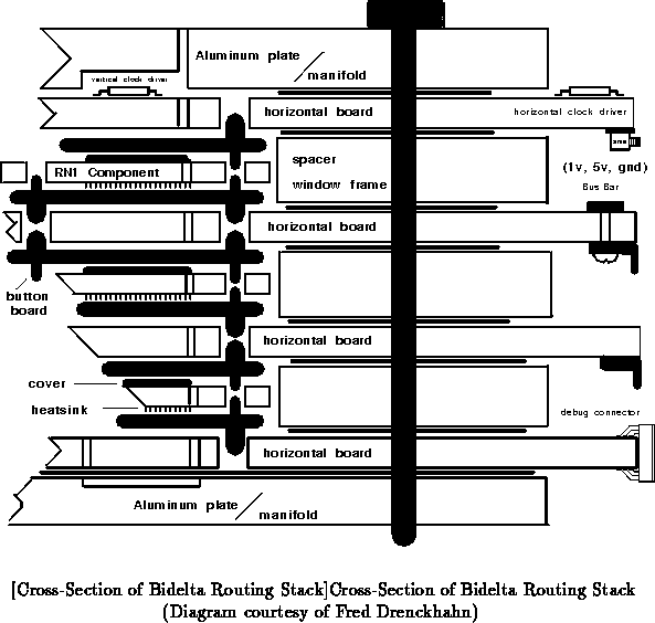
When the transmission reaches the top of the routing stack it is brought straight down, back through the stack, to connect to the destination processors. This is necessary because the set of source and destination processors will normally be the same. All routing through the layers of routing components is provided by the through routing pins on the RN1 package as described in the previous section.
Contact is made between the routing components and the horizontal pc-boards through button board carriers. These carriers are thin boards, roughly the same size as the routing chip, with button balls [Smo85] aligned to each pad on the routing chip. These button balls are 25 micron spun wire compressed into 20 mil diameter by 40 mil high holes in the button board connector. They provide multiple points of contact between each routing component and horizontal board when the stack is compressed together; in this manner they effect good electrical contact without the need for solder. This allows ease of packaging construction and component replacement.
Channels are provided both in the stack and through each routing component for liquid cooling. FCC-77 Fluorinert will be pumped through these channels to provide efficient heat removal during operation.
At the targeted clock rate of 100MHz for network operation, wire delay
consumes a significant portion of the clock cycle. Thus, the physical
size of the horizontal routing boards is an important consideration for
network performance. Additionally, with current technology for fabricating
pc-boards, it is not possible fabricate pc-boards any larger than
with reliable yield.
Each layer, including pc boards, routing components, and connectors, will be
tall. The height of a stack will be roughly:
.
A more detailed description of Transit packaging technology is given in [Kni89].
Ideally, we want to package all the hardware in a large stack. Size wise, this should be feasible. The stack with only a network will be very thin leaving plenty of vertical space for nodes. Our biggest problem, will be incorporating conventional packages into our packaging scheme.
The large MBTA machines we are considering building will support 64 processors. For these machines, the network can be housed in a single stack. The nodes can be integrated into the same stack structure by extending it vertically ( i.e. adding more stack layers. The nodes can either be placed on one side of the network, or with the network sandwiched in between. For bidelta networks, it is probably preferable to place half the nodes on each physical side of the network. In this case, half of the processor will connect to the stack through the network. The other half will have their return connection loop through the network. For fat-tree networks, the processors should all be placed on the same side. Also, it will probably make most sense to package a single node vertically up the stack ( i.e. so that each horizontal layer is composed of a cross-section of half or all of the nodes).
As described in Section , the compute and i/o processors should
be able to indicate the correspondence between the number of cycles they
require to perform an operation and the number that would be required by
the architecture being emulated. This information will be important to
accessing the performance of the architectures under study. Ideally, this
correspondence, along with the expected rate of execution of the emulated
components should allow us to normalize the operation of all system
components so that we get results which are consistent with the expected
relative performance of all components. Finding the best mechanism for
achieving this close of a correspondence of execution rates will require
further consideration.
Aside from the normalization consideration mentioned above, it should be possible to control performance measurement entirely from software. It may be desirable to set aside a chunk of memory on each processor that is invisible from the emulated machine which can be used to store statistical information. Once a run completes, this information can be collected from all nodes under software control and the information can be uploaded to the host workstation for evaluation.
In this section, I briefly detail a possible path to get us from where we are now to working versions of MBTA.
Kendall will allow us to debug a single node before we commit to larger designs. It will give us experience with the host interface and the chosen processor. It will also give us a quick path to a machine which people working on software can utilize for testing. It should also allow us to perform simple tests of the network interface.
Since Kendall is a single node, RN1 is not in the critical path for its construction. Only one version of Kendall will be constructed unless it looks like the latency to future machines will be considerable. That is, if it doesn't look like we will be waiting on RN1, effort will proceed directly from Kendall to Park. If it looks like Park will be far off, we can replicate Kendall to prevent software development from being bottlenecked by a single working machine.
Park can provide a structure for performing moderate to high speed testing of RN1. Carefully coded software on each node can be used to stream data across the routing chip, coordinate the results, and report them back to the host workstation. Park won't provide quite the flexibility of the dedicated tester under design. It will be able to stream bits to and from the routing chip at a significantly higher rate.
Park is the smallest real multiprocessor we can construct. As such, it is the version of MBTA that should be replicated for people to work and play with. It is small enough to be easily replicable (and hopefully cheap enough). It should not require special packaging or cooling so people can afford to keep one in their offices. It may be important to provide a serial interface to Park so as not to require everyone who uses it to obtain a workstation with a high-speed bus interface. However, since we are initially implementing an HPIB/GPIB interface, we should have sufficient host servers using the existing AI lab HP workstations.
Park should provide enough of the essential characteristics of a parallel machine to be used for software development, debugging, and experimentation. With his own Park board, each developer should be able to get his code and experiments running without running into bottlenecks for machine access.
Section ).
Government Center will give us an opportunity to work with integrating conventional components into our stack packaging scheme before we attempt to build a large machine. It will also allow us to debug interboard connections and the detailed node schematics in the form that they will be used in Wonderland.
It is not completely clear whether or not we need to make this intermediate stop. It is currently too early to tell how this portion of implementation will progress.
Wonderland will provide a structure for testing a full network constructed
from RN1 routing components at moderate to high speeds. Wonderland will
also provide the first real test of our three-dimensional packaging
schemes. We should be able to gain considerable experience from its
construction and day to day operation. Its regular operation will provide
a feasibility proof for this packaging scheme.
As a full 64 processor machine, Wonderland should be large enough that we can begin to get meaningful information about the behavior of large parallel computer systems. Unfortunately, due to both costs and the fact that Wonderland will be liquid cooled, we will probably be unable to build more than one version of Wonderland. Hopefully, Park will provide sufficient testing grounds that the necessity of sharing Wonderland among researchers will not pose a major problem.
The construction of Wonderland will essentially be the culmination of the
initial MBTA effort to build an experimental machine for bootstrapping into
parallel architecture design and evaluation. Hopefully, this will be the
beginning of a rich set of architectural studies and open the door for
considerable exploration and experimentation. The following
Sections and
begin to suggest further work that
can follow from the initial MBTA effort.
MBTA is not intended to be an end unto itself. It is intended to be a tool for studying components and issues in parallel computer design. In this section I begin to touch upon concrete uses for MBTA.
As mentioned when motivating the purpose of MBTA, it will provide us with considerable power to test the RN1 routing component.
The framework of Park will allow us to test the operation of a single routing component at high speed.
With the construction of Wonderland, we will be able to test an ensemble of components as they are intended to be used. This will allow complete functionality testing at high speeds of the network components. Statistical performance information can be gathered on a realistic network to further characterize the network and its behavior under various amounts of loading and access paradigms.
The day to day operation of Wonderland will provide valuable experience with this packaging structure.
It will serve as a feasibility test of the packaging scheme. We will
become aware of difficulties overlooked at the conceptual stage and have
the opportunity to overcome them. Since Wonderland is intended to be used
regularly for experimentation, this environment and usage constitute a
complete field test.
While RN1 provides the low level network building block, the issue of higher level network protocols remains fairly open. With a physical RN1 network implemented, MBTA will provide the ability to implement and test various protocols that might be used on top of the RN1 network.
One consideration is that of fault localization. RN1 provides sufficient information to localize faults, but this must actually be done at a higher level. The collection of fault information from each node and global assemblage also needs to be considered.
Certainly, one of the primary uses for MBTA is as a tool to experiment with designs for the processors in a parallel computer system.
In addition to experimenting with various processor architectures some experimentation needs to be to determine the appropriate division of work between the compute and i/o processors.
With the appropriate software compilation or interpretation, MBTA will allow us to study various processor architectures. Single processor behavior is one important concern. MBTA will give us the ability to study the performance in the context of a full parallel machine.
With a generic programmable processor to emulate the i/o processor, MBTA offers considerable freedom to study various behaviors for the i/o processor. This should allow us to experiment with a number of caching schemes and coherence protocols. We can experiment with garbage collection techniques and the extent to which the i/o processor can make garbage collection invisible to the computing processor. Experimentation can be done with the manner in which a node handles traffic to and from the network.
MBTA will provide a test bed for parallel computers. With the processors programmed to emulate their respective architectures, we have a system to run code for any emulated architecture. Work on compiling for parallel systems can use MBTA to execute the compiled code and study the effects of various compilation techniques. This also provides considerable room for compilation efforts to provide feedback to the architectural development. Ideas and optimizations motivated by compiler development and interaction can easily be tested by simply modifying the processor emulations.
Parallel language design is facilitated by the ability to reasonably emulated target machines. In fact with MBTA's emulation flexibility, it should be possible to consider multiple architectural targets. MBTA should be able to provide considerable feedback on the relative merit of various schemes and the interaction of the various system components.
Attempting to actually run code on a parallel system, such as MBTA, will require that many operation details be worked out. Scheduling tasks on parallel systems and load balancing among processors remains a very open area of study. MBTA should provide us with a moderately accurate emulation of a parallel system on which to study these issues.
The requirements of parallel program execution is still not well understood. In order to better our understanding of these requirements, we need to develop a good retinue of parallel programs for study. The current lack of existing parallel programs results from the lack of parallel computer systems on which to run them. With MBTA, we have a machine to execute parallel programs with some efficiency. MBTA should allow us to develop and debug a number of parallel applications. These applications should in turn provide valuable feedback on the program behavior in parallel computer systems and perhaps provide insights into how parallel computers can be optimized.
I personally look forward to seeing the development of parallel CAD tools. Another pipe dream I have is that we could have a PARACAD system running for our processor architecture on Wonderland when we are ready to actually layout and fabricate a processor.
One of the valuable contributions of MBTA for all these experiments is the ability to provide performance statistics for various components and the performance of interacting components. MBTA should be able to provide us with moderately accurate data on the performance of various architectural ideas.
Once we have the basic MBTA machine constructed, the doors are opened for quite a number of small to moderate sized improvements and extensions to be made. In this section, I introduce a few that might be worth pursuing.
Section suggested the possibility of eventually providing an
ethernet interface for MBTA machines. Ethernet could be a worthwhile
addition to MBTA. With a number of ethernet controller components on the
market, the hardware itself should not require major effort. The software
to support all the services to which we are accustomed, would be a mammoth
task. However, this could probably be partitioned into a number of
reasonable sized pieces and we could eventually build up the functions that
seem most useful.
Section suggested that it would be desirable to have a
compiler which would take a caching protocol at the state diagram level and
compile it into the appropriate code to allow the i/o processor to
implement it.
As mentioned in Section , MBTA does not provide any form of
secondary storage. Eventually, it might be nice to consider the use of
virtual memory with a parallel machine or at least experiment with the
implementation of secondary storage.
Adding secondary
storage to an MBTA machine such as Wonderland should quite feasible. This
will, of course, raise quite a number of packaging, interconnection, and
topology issues.
It should be possible to reuse much of the MBTA design when building real high performance parallel computers.
Future version of the routing component may behave differently than RN1 and require a somewhat different interface. MBTA design should be cleanly adaptable to such changes. Unfortunately, the low level chip interface will probably have to change. However, beyond that small amount of hardware, the rest of the changes should impact only on the detailed programming of the i/o processor.
After experimenting with different processor architectures, we will eventually fabricate components with the architecture(s) that looked most promising during emulation. At this point, we will need to integrate these components into a parallel computer for testing, analysis, and actual use. Ideally, we should be able to easily replace an emulation processor with the fabricated component. This should allow us to get the new component integrated into a functional system in a moderately short amount of time.