MBTA: Message Formats
Andre DeHon
Original Issue: June 1990
Last Updated: Tue Nov 9 13:01:26 EST 1993

This note documents the format of data streams sent across the network between the network interfaces, net-in and net-out (tn24) (tn23). In essence, this document describes the transmission sequences for the network level transactions described in (tn19).
The bytes of a network message can be classified as follows:
The destination specifies the node in the network to which the network
message is directed. This byte quantity is simply the high 8 address bits
(ADDR) of the global shared memory address for memory operations.
This byte is interpreted directly by the routing network as the routing
byte.
N.B. This limits the number of nodes to 256. This should not pose any long term limitation since we will certainly have revised many of these details (including going to a larger address space) by the time we build a machine with more than 256 nodes.
Table provides a tentative encoding for operations. These
operations correspond exactly to those suggested in (tn19). The
operation encoding for an rop is passed straight through to the
network processor. The processor then interprets this encoding to
determine the exact function specified.
For read and write operations, there will be three bytes of address to specify the address of data on the remote node.

The data associated with each operation will be transmitted with each word broken into four byte chunks.
For read and write operations, a length byte specifies the number of consecutive memory words to read or write.
The integrity of each network transaction is verified with a forward
checksum (tn6). The checksum is only a single byte wide. For the
moment, we will consider generating this checksum using the same CRC
checksum generator used by RN1 [Min90]. Since RN1 makes use
of a 14-bit checksum instead of an 8-bit checksum, the forward checksum
will utilize only bits 9:2 of the generated checksum.
Often, the node may not be able to respond immediately to a network
operation. When the node cannot supply the requested data to the source
immediately, it must be capable of telling the source to wait. To allow
this specification, two flow control signals are defined (see
Table ). After an operation is requested, Wait will be
transmitted to the source until the destination node can field a reply.
Once ready to reply, the destination node sends continue to indicate
that it has a response which will arrive immediately. Some operations
require no data in a response. Ack provides a succeed/fail response
to indicate the completion of such operations. Ack is used generically
to refer to responses which can be ack_t or ack_f (see
Table
).
RN1 defines the message components shown below. The ninth bit shown here is the control bit. This bit is always high while RN1 is transmitting data and low when signalling occurs or no data is being transmitted [Min90].
This section describes the format of network transactions ((tn19)) using the components described in the previous sections.
Following is a noop operation sequence as seen from the interface
between the sending node and the network. denotes the number of
network stages.
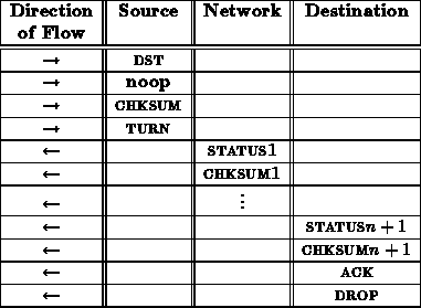
This same sequence for a noop operation looks like the following from the interface between the network and receiving node.
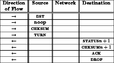
This sequence assumes a path is available on the first try through the network. If the transaction was blocked at some routing component in the network, a DROP would have been generated by the blocked router following its CHKSUM.
Note that the status/checksum pairs numbered 1 through come from
the successive routers in the network. The status/checksum pair labeled
comes from the network interface at the destination node. See
(tn24) for a description of these status and checksum bytes.
A noop transaction should always succeed. Thus, the ACK should always be ACK_T.
A reset transaction looks very similar to a noop transaction.
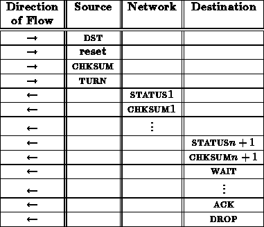
From the interface between the network and receiving node, this reset sequence looks like:
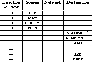
The ACK here indicates whether or not the processor succeeds in booting when reset. Consequently, the connection is held open sending WAIT signals while the processor goes through its boot sequence.
A read transaction might proceed as follows:
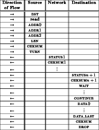
From the interface between the network and receiving node, this read sequence looks like:
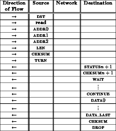
The final checksum might appear a bit excessive. The connection integrity has been verified with the previous checksums. However, it is necessary to make completely certain that no glitches or faults occurred during the data transfer.
A write transaction might proceed as follows:
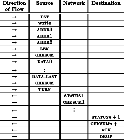
From the interface between the network and receiving node, this write sequence looks like:
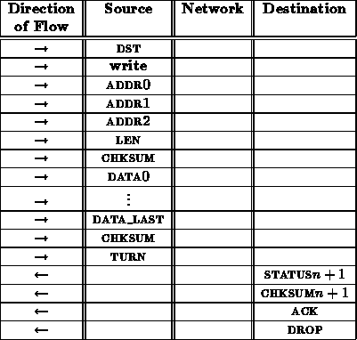
The ack here may be unnecessary. It provides a final opportunity for the receiving node to indicate that it wasn't able to deal with the write transaction and the operation should be repeated.
It is necessary to specify the length ( LEN) of the data to be written in order to guarantee that faults in the network ( e.g. a control bit stuck asserted) don't cause a write operation to write over important data in the node's memory. A checksum is included immediately after the address and length specification to protect the receiving node's memory. This checksum comes before the data and is used to assure that the address and length have been received correctly before anything is overwritten in memory. This prevents transmission errors from overwriting random sections of a node's memory.
An rop transaction might proceed as follows:
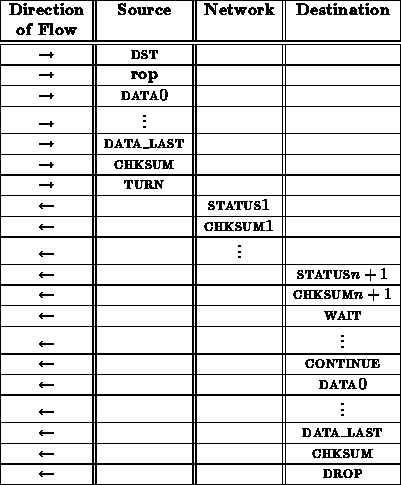
From the interface between the network and receiving node, this rop sequence looks like:
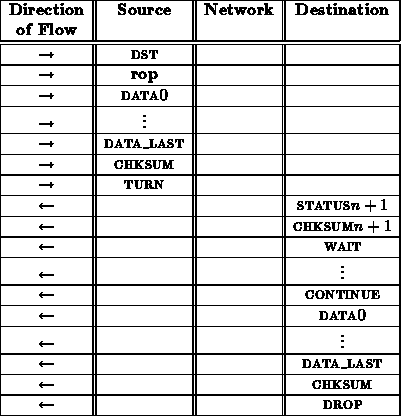
As in the case with the read operation, the inclusion of the last CHKSUM is useful to guarantee the integrity of data returned over the open connection.
This transaction should be capable of continuing to turn the connection around as many times as the software needs.