T-Station
The MBTA Host Interface
Andre DeHon
Original Issue: June 1990
Last Updated: Wed Nov 10 22:37:27 EST 1993

This document describes the T-Station host interface which connects an MBTA computer to a host computer. Interface composition and programming model are described here. This document does not address the specifics of a particular host interface bus.
The MBTA host interface will provided a memory mapped i/o interface to one or more nodes of MBTA. The host interface will function entirely as a slave device on the host's bus. This gives the interface both conceptual and architectural simplicity while maintaining reasonable flexibility.
A look at the host bus interface specification for some of the possible interface busses implies that we cannot directly map all the memory on an MBTA node (or nodes) directly into the host computer's address space. i.e. some host busses only allocate a moderately sized chunk of the address space for each peripheral; the range of addresses so allocated is insufficient to cover all of the memory on even a single MBTA node. However, we want to be able to access the entire memory of an MBTA node for bootstrapping and debugging.
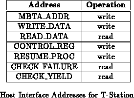
To get around this potential address space limitation, we incorporate an address_ register into the host interface. The host address MBTA_ADDR, is written to initialize the address_register, specifying the address of interest in MBTA's memory. When the host writes to MBTA_ADDR, the host interface latches the data into its address_register. To write to MBTA memory, the host writes to the host address WRITE_DATA. The host interface takes the specified datum and writes it into MBTA memory at the address contained in the address_register. At the end of the write operation, the value in the address_register is incremented. Incrementing the address register at the end of every write operation allows consecutive sequential write operations to be performed without the need to respecify the target MBTA address. Similarly, if the host wishes to read data from the MBTA node, the host first sets the address in the address_register by writing the appropriate address to MBTA_ADDR. The host then reads from the host address READ_DATA. At the end of a read operation, the address_register is incremented to allow consecutive sequential reads.
A number of control functions are needed to control the MBTA boot node.
The host needs to be able to reset the processor and network. To control
these resets and suspend the processor, the host has a 3-bit register known
as the control_register. Writing to CONTROL_REG will
update the value of the control_register. The
control_register gives explicit control of network and processor resets
to software. Software should make sure that the processor's memory is
loaded with the appropriate boot code before the processor is allowed to
boot. Figure shows the composition of the
control_register.

When T-Stations first comes on, the control_register should
initialize itself with the value 0b100. That is, the host interface should
come up with both and
asserted and
deasserted .
The 80960CA provides no means for suspending the processor, per se. To effect a processor suspension, we have the processor's external memory control handle a read to from the host interface in a special manner. When the processor reads the HOST_REQUEST address, the control logic does the following:
The host completes its operation by writing a status word at
HOST_REQUEST then asserting .
The assertion of
signals the control logic
to complete a read operation to HOST_REQUEST and return
to its normal behavior, allowing the processor to continue execution.
When the host first takes over the node's bus, it should read the node
memory location HOST_OP. The word stored at this location should
indicate the operation which the node wishes to perform ( e.g.
input, output, trace breakpoint). If the host requested the processor
suspension by asserting , the host presumably
already knows why the node suspended.
When the host relinquishes control of the bus to the node processor, it passes the processor a return value through HOST_REQUEST. The host and node software can coordinate to give this value arbitrary meaning. Among other things, this return word should be used to signal the processor to reload various configuration registers from known locations in the node's memory.
T-Station may be MBTA's only window to the outside world. As such, it must
allow MBTA to control the input/output operations which MBTA requires. The
read and write primitives of Section are sufficient to move
data between the host and MBTA but do not allow MBTA to specify
when and where to transfer data. To give MBTA the requisite i/o control,
we provide four i/o transfer address and define input and output host
operations.
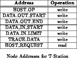
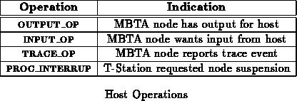
For output, two words are allocated in the node's memory to hold pointers which delimit the data in the node's memory which MBTA wishes to transfer to the host computer. DATA_OUT_START holds the starting address of the output data while DATA_OUT_END marks the end of the output data. When the MBTA processor wishes to output data to the host, it writes the start address of the output data to DATA_OUT_START and the ending address to DATA_OUT_END. It then writes the value OUTPUT_OP to HOST_OP to signal the host it wishes to perform an output operation. The processor then reads the HOST_REQUEST address to effect the transfer. As control returns to the processor, it deals with the host return word accordingly.
MBTA can request input via the host interface in a similar manner. Again, two words in the node's memory are allocate to delimit an input buffer into which the host may place data. The DATA_IN_START location holds the address of the beginning of the input buffer. DATA_IN_LIMIT denotes the extent of the input data buffer. When the MBTA processor wishes to receive input, it first writes the input buffer starting address to DATA_IN_START. Then it writes the ending address to DATA_IN_LIMIT. To effect the input operation, it then writes INPUT_OP to HOST_OP and suspends itself by reading HOST_REQUEST. Again, when control is returned to the node, the processor deals accordingly with the host return word.
To indicate the length of data transferred by the host, the first word in the input buffer should indicate the size of the data placed in the input buffer. In cases in which the host wishes to transfer more data than the specified input buffer will hold, the host simply fills the input buffer and writes the size of the data it would like to have written into the first word of the input buffer. In this case, the node processor will note that the specified length is greater than the buffer size. The processor is thus informed both of the fact that the entire allocated input buffer is full and of the amount of additional memory the host needs to complete the memory operation. The MBTA node processor is then free to allocate more memory and get the rest of the input from the host or process some of the data in the input buffer before retrieving the rest of the input data from the host. The host simply holds its remaining input data until the node processor allocates space for more input and requests the input.
Tracing is supported in a manner similar to output. When a trace interrupt occurs, the trace fault handler behaves roughly as follows:

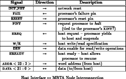
Table shows the interconnection between the host
interface and an MBTA node.
,
, and
connect
straight from the control register outputs to the corresponding pins
on the processor. HREQ, W/
,
, and
connect into the nodes bus control
logic. Providing only bits 23 through 2 of the address allow the entire 16
megabytes (4 megawords) of memory on a node to be addressed. The bus
control logic automatically selects the SRAM logic for addressing from the
host interface so the high address byte is unneeded. Only word addressing
is allowed from the host interface so the lowest two address bits and
individual byte enables are not needed.
Tables and
summarize the MBTA
interface addresses that compose the host interface. Table
summarizes host operations. Table
summarizes the T-Station
registers.


While the processor is halted or suspended, the host is free to perform any
operation. While the processor is running, the host is only free to suspend
or halt the processor and reset the network. That is, there is no
interlocking between the host interface and the processor for access to the
node's bus resources. The host and processor should never attempt to use
the node's bus simultaneously. If HREQ or is asserted, the host has access to the node's bus; otherwise, the
node's processor has access to the node bus and T-Station should tri-state
its address and data lines.